Metallurgical oven and a material basket for a metallurgical oven

a metallurgical oven and oven technology, applied in the field of metallurgical furnaces, can solve the problems of insufficient volume defined by the vessel and the cover to receive the entire amount, inconvenient low temperature, and the possibility of damaging the retaining member and/or the shaft walls, etc., and achieves the effect of simple and inexpensive manner and large internal heigh

Inactive Publication Date: 2008-05-20
SIEMENS VAI METALS TECHNOLOGIES GMBH & CO
View PDF11 Cites 3 Cited by
  • Summary
  • Abstract
  • Description
  • Claims
  • Application Information

AI Technical Summary

Benefits of technology

[0048]In a metallurgical furnace according to the present teachings, the retaining means can be pivoted back immediately after the charging operation in order to close the charging apparatus. This design results in a configuration of the charging apparatus with suitable interchangeable material baskets, in which the corresponding material basket can be exchanged immediately after the unloading operation. In addition, this design provides an empty space in the upper region of the projection, in which space it is possible to influence the waste gas.
[0049]When the charging apparatus is designed with the interchangeable material baskets, there is no need to provide cooling means for the retaining means and the shaft, because they do not heat up so greatly so as to require cooling, due to relatively short residence time above the projection.
[0050]In addition, when the charging apparatus is designed with the interchangeable material b...

Problems solved by technology

Because the volume of the smelted material, particularly in the case of scrap, is substantially less than in the non-molten condition, the volume defined by the vessel and the cover is not sufficient to receive the entire amount of charging material for a smelting operation.
As a result, there is a possibility of damaging the retaining member and/or the shaft walls.
For known reasons, that low temperature is disadvantageous with respect to pollutants, in particular so-called VOCs (Volatile Organic Compounds).
The waste gas that passes through the shaft and the cold charging material is far from being at the appropriate temperature, such that a considerable introduction of energy is required into a post-combustion chamber in order to destroy the ...

Method used


Image

  • Metallurgical oven and a material basket for a metallurgical oven
  • Metallurgical oven and a material basket for a metallurgical oven
  • Metallurgical oven and a material basket for a metallurgical oven

Examples


first embodiment

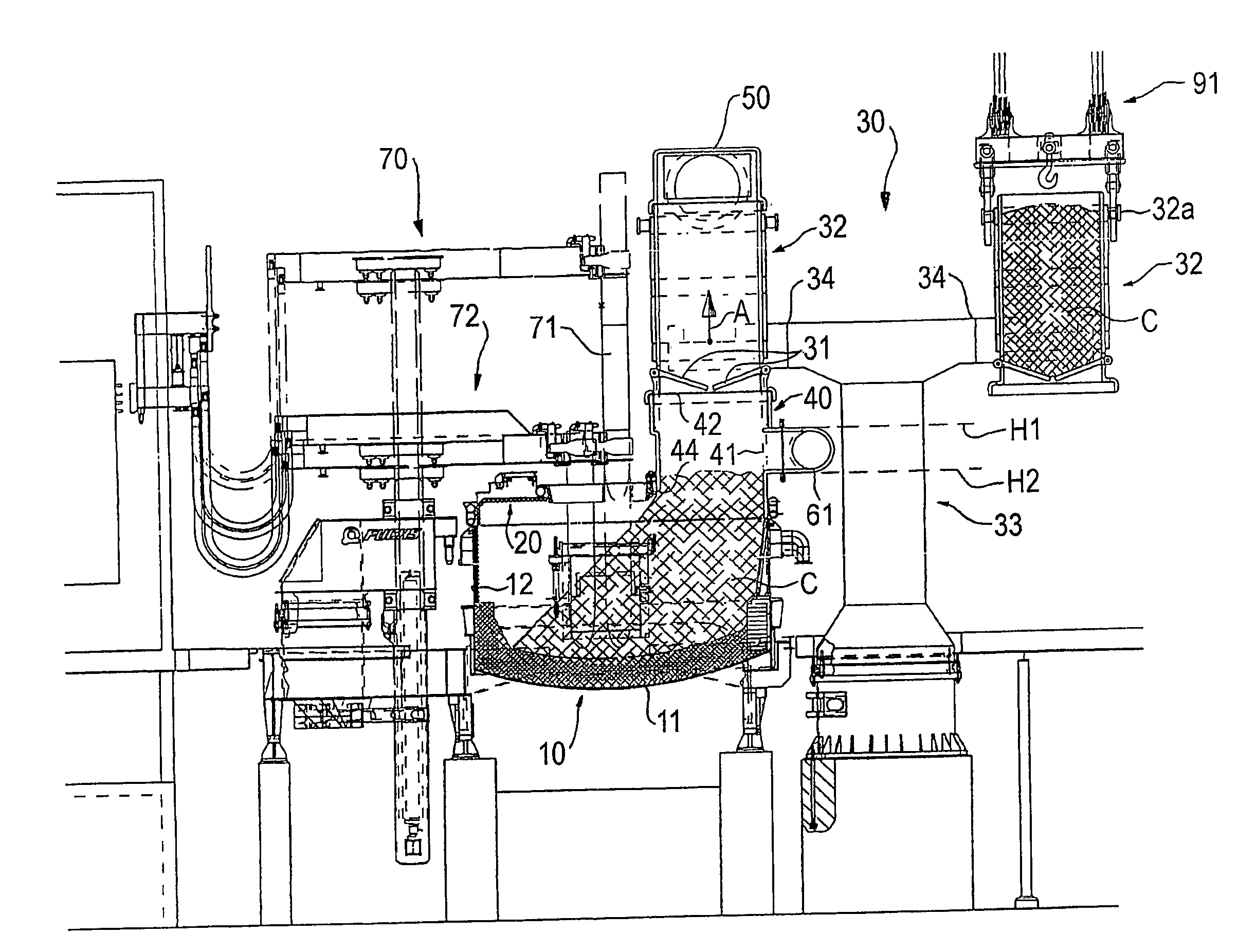
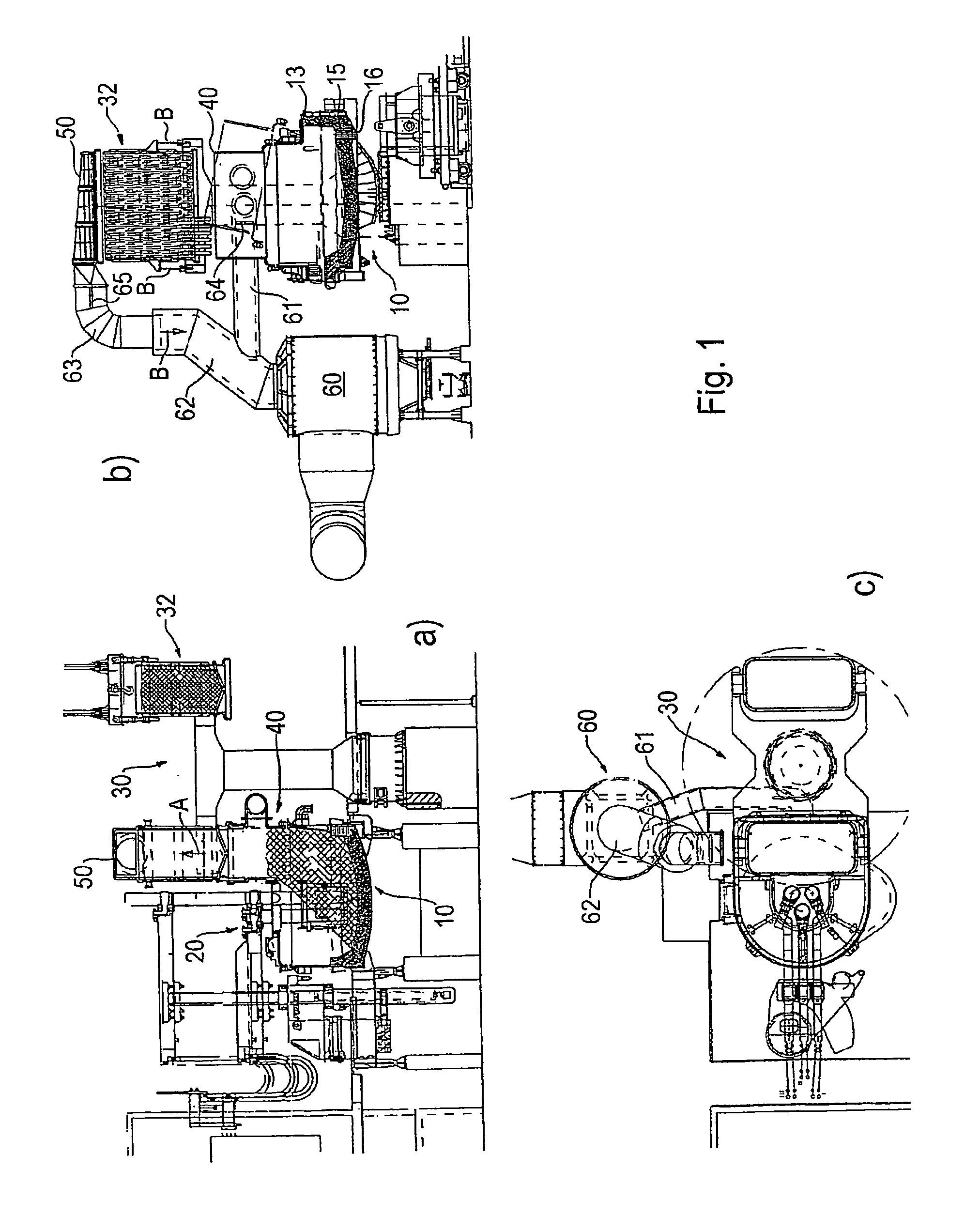
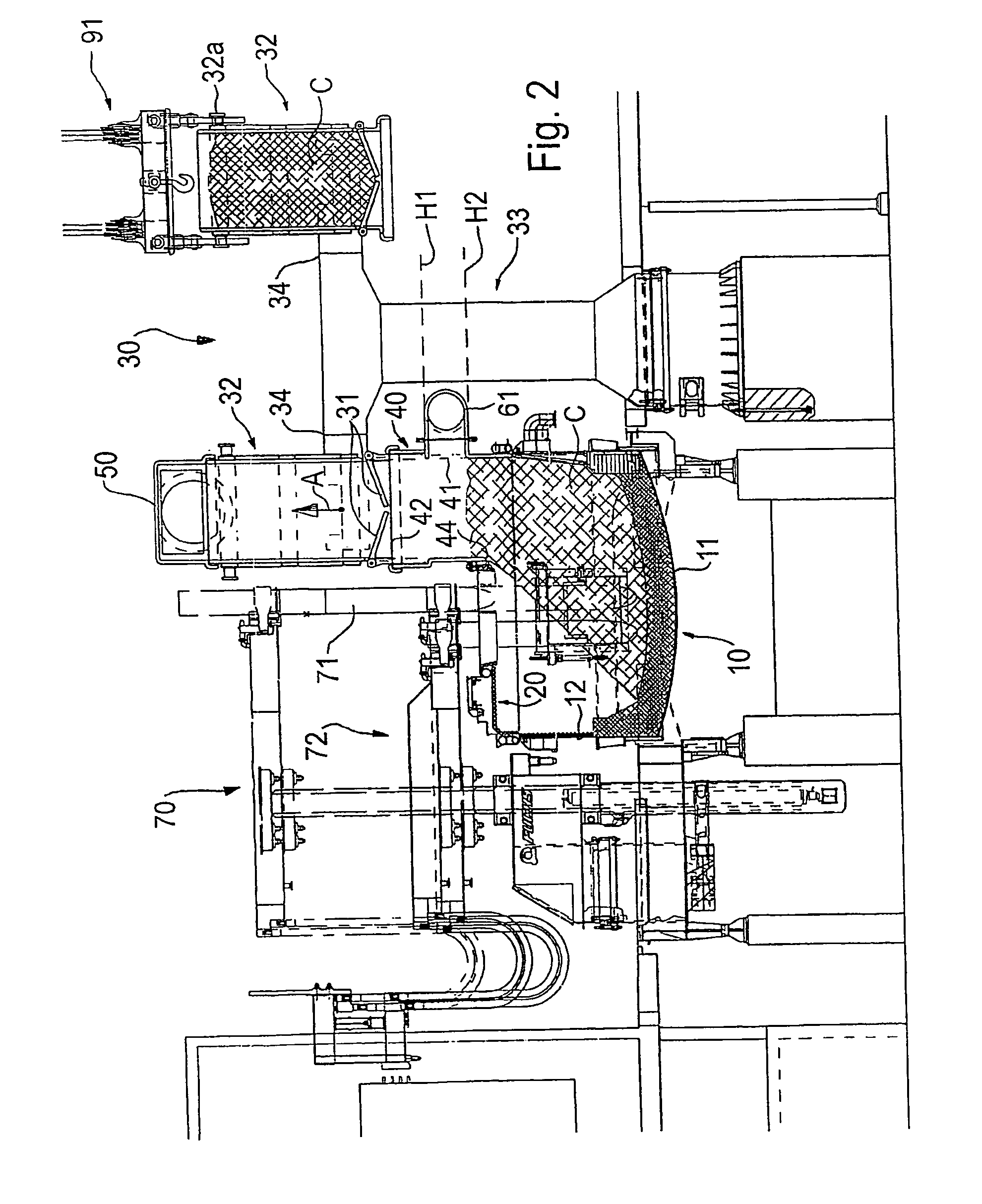
[0023]Described hereinafter with reference to FIGS. 1 to 8 is a metallurgical furnace according to the invention, which represents the preferred embodiment.

[0024]FIGS. 1 to 4 show the first embodiment in a first configuration in which material baskets 32, which can be positioned by means of a changing device 30 above a projection 40, are used as the shaft.

[0025]FIGS. 5 to 8 show a second configuration of the first embodiment, in which the charging opening 42 of the projection is closed by means of a cover 43 in the melting operation in the manner of a conventional arc furnace that does not have a shaft. That configuration can be used to continue operation when maintenance procedures are to be performed on the changing device and / or the material baskets or the like.

[0026]The first configuration will now be described with reference to FIGS. 1 to 4.

[0027]The first embodiment is formed as an arc furnace 1 with a furnace vessel 10 supported on a furnace cradle 2. The furnace vessel 10 co...

second embodiment

[0064]the arc furnace of the invention is shown in FIG. 9. As has already been described above, in this embodiment the changing device 33 is provided with cantilever arms 34 that are individually pivotable about a horizontal axis 36. The arms 34 also can be jointly pivoted as an arm of a rocker member about the axis 36.

[0065]As can be clearly seen from FIG. 9, and this applies with respect to all embodiments of the invention, the structural height above the shaft can be markedly reduced because there is no need to provide space for an additional scrap basket or charging material container that is held by the crane 90 above the shaft or material basket 32 during the charging operation.

[0066]FIG. 9 shows a cover suction arrangement 100 that is connected via a waste gas conduit 101 to a waste gas disposal system. The waste gas disposal system can be, for example, the post-combustion chamber 60 or another apparatus.

[0067]In all embodiments, such an arc furnace is designed for a specific...


PUM

PropertyMeasurementUnit
Temperatureaaaaaaaaaa
Thicknessaaaaaaaaaa
Massaaaaaaaaaa

Abstract

A metallurgical furnace has a cover (20) for a vessel (10) and a charging device (30) for charging material that will be melted in the vessel. The charging device has a rotatable retaining means (31) and a projection (40) is provided at a charging opening (42). The furnace has a maximum filling level (H2) and the rotatable retaining means is pivoted into the projection for the charging operation. The pivotable range of the retaining means does not extend below the maximum filling level (H2). At least two self-supporting material baskets (32) can be positioned in a removable manner above the projection (40), and each comprises an inner chamber that can be closed on the lower side thereof by the retaining means (31) and a volume (C) for receiving the charging materials. A change device (33) interchanges and positions the material baskets (32).

Description

CROSS-REFERENCE[0001]This application is the national stage filing of International Application No. PCT / EP02 / 09255, which was filed Aug. 19, 2002 and claimed priority to German Patent Application No. 101 40 805.6 filed Aug. 20, 2001.TECHNICAL FIELD[0002]The invention concerns a metallurgical furnace, in particular an electric arc furnace, and a material basket for the metallurgical art.DESCRIPTION OF THE RELATED ART[0003]A metallurgical furnace, such as the electric arc furnace known from WO 98 / 08041 A1, has a vessel that comprises a lower vessel portion and an upper vessel portion, a cover for the vessel and a charging apparatus, which is in the form of a shaft and in which a pivotable retaining means is arranged. In the smelting operation for such apparatus, the entire charging material (for example, scrap) is charged in one operation. Because the volume of the smelted material, particularly in the case of scrap, is substantially less than in the non-molten condition, the volume d...

Claims


Application Information

Patent Timeline
IPC IPC(8): C21C5/46C21C5/52C21C5/56F27B3/06F27B3/08F27B3/18F27D3/00F27D3/06F27D13/00F27D17/00
CPCF27B3/065F27B3/085F27B3/186F27D3/06F27D17/003C21C5/527F27D3/0028Y10S266/901Y10S266/90Y02P10/20
Inventor FUCHS, GERHARD
Owner SIEMENS VAI METALS TECHNOLOGIES GMBH & CO
Why Eureka
Try Eureka