
Mutual interference processor for pulse radar

a pulse radar and processor technology, applied in the field of interference suppression in sensors, can solve problems such as contamination of received energy signals, and achieve the effects of reducing the effect of pulsed interference, removing or reducing pulsed interference, and removing or reducing clutter signals

Active Publication Date: 2008-05-20
LOCKHEED MARTIN CORP
View PDF3 Cites 35 Cited by
  • Summary
  • Abstract
  • Description
  • Claims
  • Application Information

AI Technical Summary

Benefits of technology

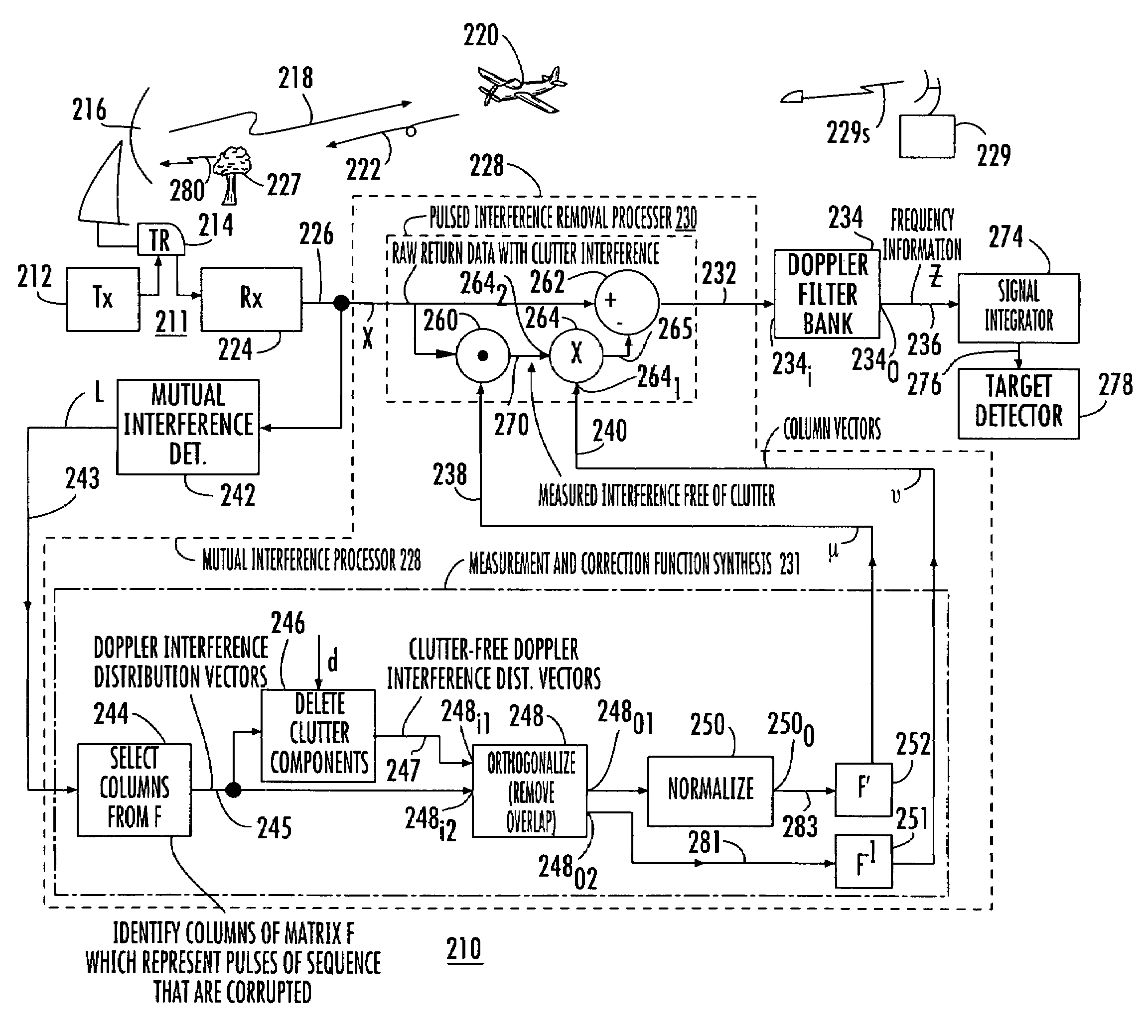
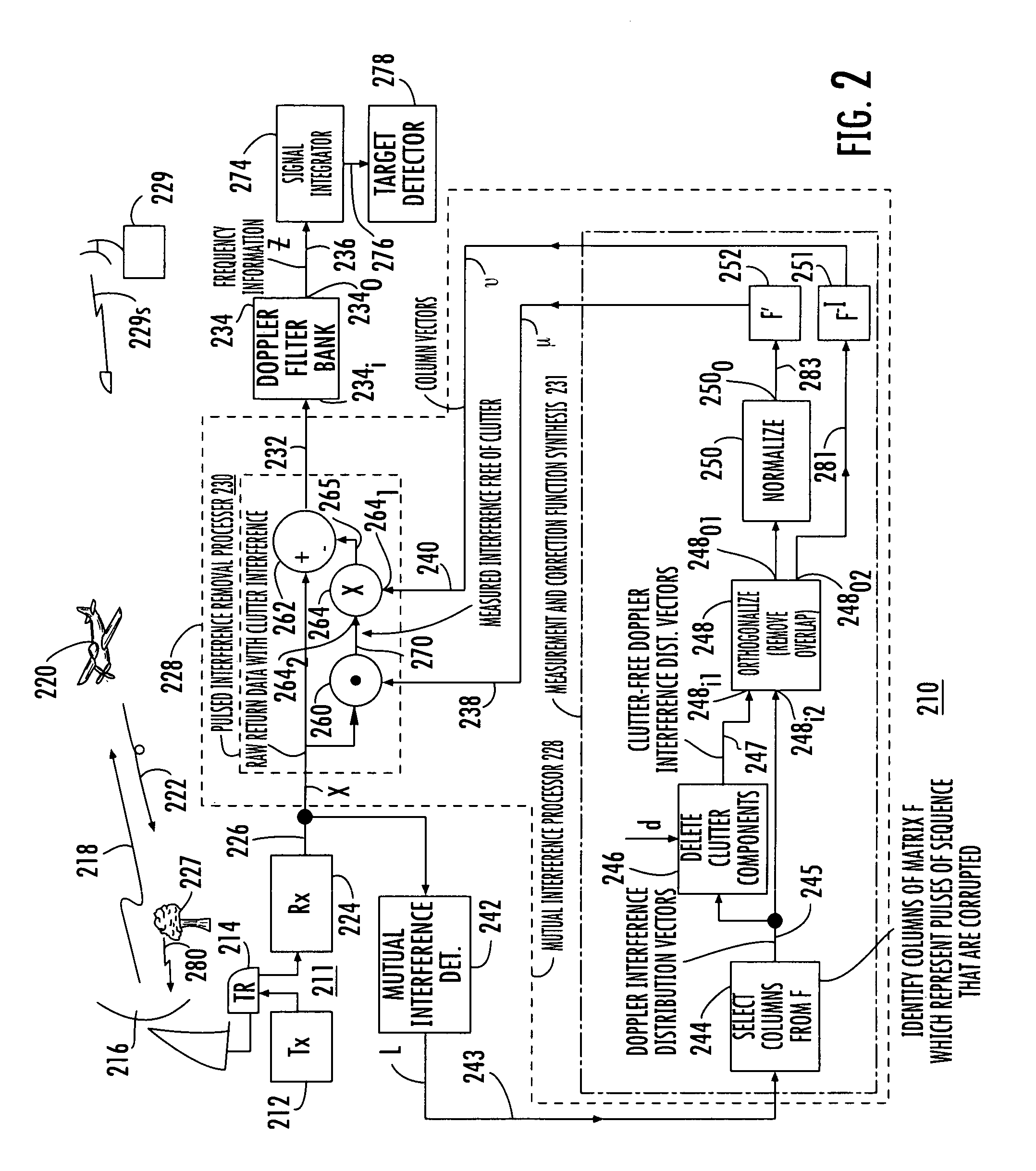
[0009]A method according to another aspect of the invention for sensing remote target(s) in the presence of interfering and clutter signals comprises the steps of radiating sets of sequential pulses of energy toward the target, and receiving reflected energy containing amplitude and phase information relating to the target to thereby generate received energy signals, which may be at baseband or at an intermediate frequency, and which may be analog or digital. The identity(ies) of those pulses of the sequence which are contaminated with pulsed interference are extracted from the received energy signals and listed. A pulse-Doppler filter bank including a plurality of filters is provided, where each of the plural filters is associated with a different frequency range, some of which frequency ranges are associated with clutter signals. A matrix corresponding to the pulse-Doppler filter bank is identified, in which each column of the matrix corresponds to a pulse of the sequence, and in which each row of the matrix corresponds to a frequency range different from that of other filters of the pulse-Doppler filter bank. Those column(s) of the matrix corresponding to the contaminated pulses of the sequence are identified. Those rows of the identified column(s) of the matrix which correspond to the Doppler frequencies of the clutter are set to zero and orthogonalized to remove or reduce projection overlap or interdependencies, and are then normalized to produce frequency-domain pulsed interference measurement signals. The identified columns(s) of the matrix are also directly orthogonalized to remove projection overlap or interdependencies and produce frequency-domain pulsed interference correction signals. In a mode of the method the frequency-domain measurement and correction signals are converted to the time domain. The resulting time-domain measurement signals are then applied to the received energy signals in the time domain in order to obtain amplitude and phase estimates of the pulsed interference. The amplitude and phase estimates are used to adjust the time-domain correction signals. The time-domain correction signals are then combined or processed with the time-domain received energy signals to remove or reduce the pulsed interference. The resulting received energy signals with nominally reduced or removed pulsed interference are then applied to the pulse-Doppler filter bank to remove or reduce the clutter signals. In another mode of the method the received energy signals are first processed by a pulse-Doppler filter bank to thereby remove or suppress the clutter signals and produce frequency-domain received energy signals. The frequency-domain measurement signals are then applied to the frequency-domain received energy signals in order to obtain amplitude and phase estimates of the pulsed interference. The amplitude and phase estimates are used to adjust the frequency-domain correction signals. The adjusted frequency-domain correction signals are then combined or processed with the frequency-domain received energy signals to tend to reduce the effect of the pulsed interference and to aid in extraction of information relating to the target from the phase and amplitude information in the frequency-domain received energy signals. The step of combining may consist of a difference or subtraction.

Problems solved by technology

The received energy signals may be contaminated by clutter signals at Doppler frequencies of clutter, and by pulsed interference.

Method used

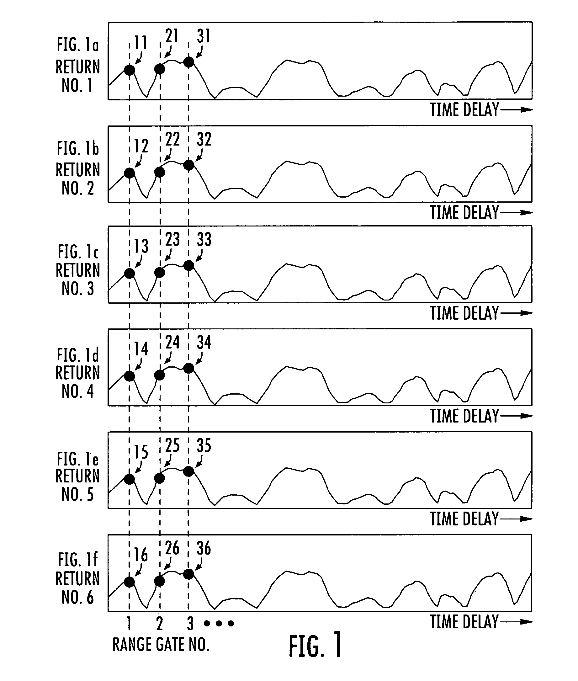

Image

  • Mutual interference processor for pulse radar
  • Mutual interference processor for pulse radar
  • Mutual interference processor for pulse radar

Examples


Embodiment Construction

[0016]This invention tends to reduce or remove pulsed interference by a process that is compatible with pulse-Doppler filter suppression of clutter signals, and thereby maintains radar target detection sensitivity during combined clutter and pulsed interference conditions.

[0017]In general, pulse-Doppler radar signals consist of trains or time-series sequences of signals, such as pulses, that can be used to measure the Doppler frequencies of target objects in order to filter clutter signals from target signals. In a typical operating scenario, after the first pulse is transmitted, its reflected signal return is then received until the time at which the second pulse is transmitted. After the second pulse is transmitted, its reflected signal return is then received until the time at which a third pulse is transmitted. This transmission and reception cycle is continued until all pulses in the sequence are transmitted and received. Alternatively, several or all pulses in the sequence may...


PUM


Abstract

Pulsed or mutual interference in a pulse radar system is ameliorated by a process that includes a pulse-Doppler filter, some frequency bins of which correlate with clutter. Pulsed interference is identified, and the corresponding column vectors of a pulse-Doppler-filter-equivalent matrix are identified. The row values of the corresponding interference-affected column vectors that correlate with clutter are nulled. The vectors are orthogonalized, and then converted to measurement and correction signal vectors for application to the pulse-Doppler received signals. Vector dot products of the measurement signal vectors with the received signals are calculated, to produce pulsed interference measurements that are nominally free of clutter. The pulsed interference measurements are combined with the correction signals which are then subtracted from the received signals to produce signals that are nominally free of pulsed interference. In one embodiment, the pulsed interference-free received signals are applied to a pulse-Doppler filter to suppress the clutter signals.

Description

FIELD OF THE INVENTION[0001]This invention relates to interference suppression in sensors such as radar, sonar, and lidar.BACKGROUND OF THE INVENTION[0002]Radar (including sonar and lidar) has been known and used by man for 60 years or more. During this time, many improvements have been devised for correcting various sensor deficiencies and frailties. Among the early improvements was the suppression of clutter by adoption of moving target indication (MTI), which tended to suppress the display of targets which had little or no motion, as measured by lack of a pulse-to-pulse phase shift in the reflected signal echo. The problem of the inverse-fourth-power amplitude of the signal returns was substantially solved by increasing the gain of the radar receiving systems as a function of the fourth-power of time following transmission of each energy pulse, in order to maintain relatively constant amplitude of the target signal returns during processing.[0003]Among the remaining problems of r...

Claims


Application Information

Patent Timeline
Patent Type & Authority Patents(United States)
IPC IPC(8): G01S13/52G01S13/00
CPCG01S7/2928G01S13/5244
Inventor LOBERGER, DAVID G.
Owner LOCKHEED MARTIN CORP
Learn More