Target detection system using radar and image processing
a detection system and target technology, applied in the field of target detection system, can solve the problems of low detection accuracy of a far target, low detection accuracy of a near target, and erroneous recognition, so as to prevent erroneous recognition, reduce detection time, and improve reliability
- Summary
- Abstract
- Description
- Claims
- Application Information
AI Technical Summary
Benefits of technology
Problems solved by technology
Method used
Image
Examples
embodiment 1
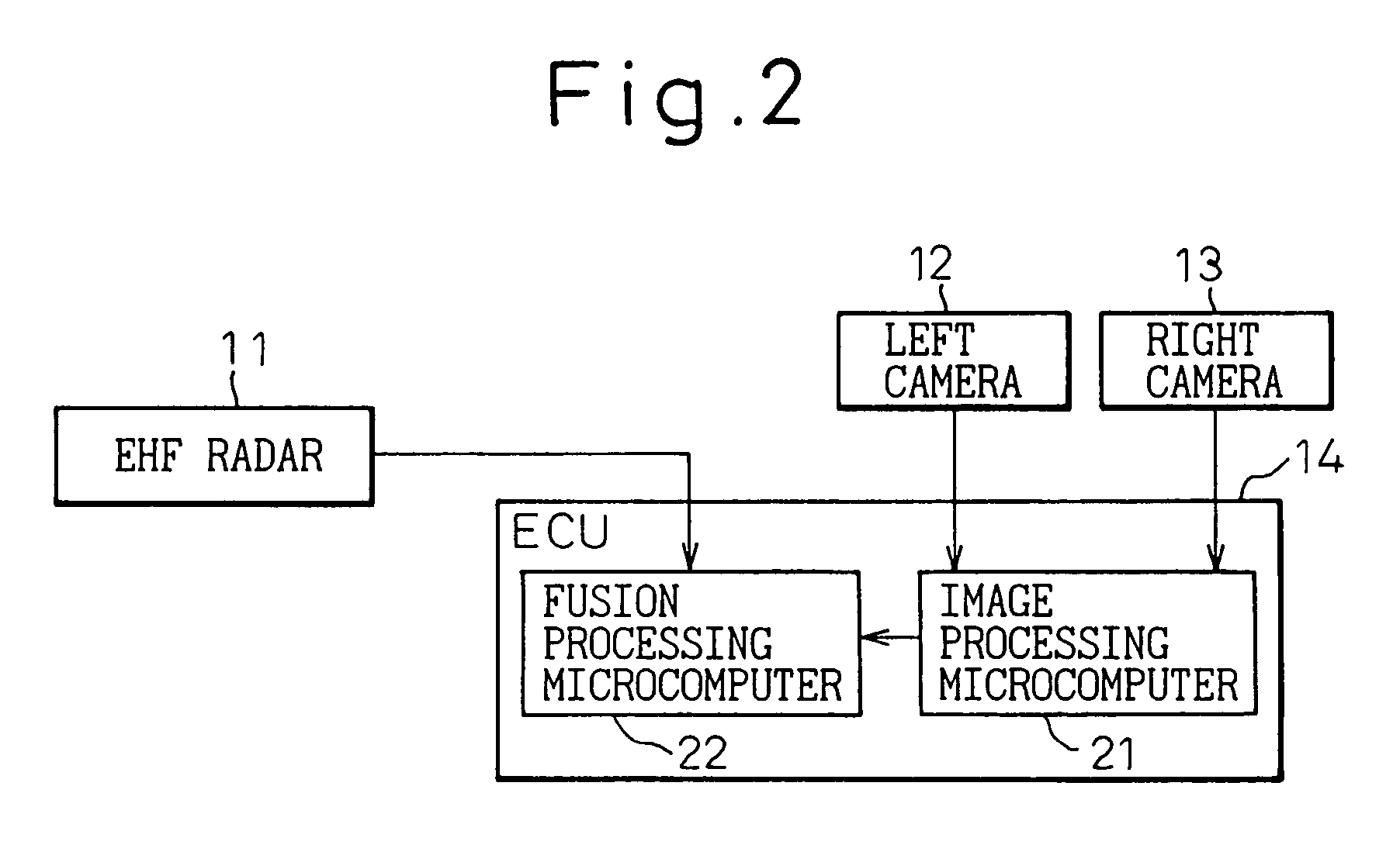
[0057]FIG. 7 shows a vehicle target detection system according to a first embodiment of the invention.
[0058]A vehicle target detection system comprises an EHF radar 11, a left camera 12, a right camera 13 and an image processing ECU 14. The ECU 14 is configured with a microcomputer 15 having the dual functions of image processing and fusion processing. Although the two cameras 12, 13, left and right, are used for measuring the distance by parallax in image processing, only one camera will do in the case where the distance is not measured by parallax.
[0059]Now, the processing in the microcomputer 15 will be explained.
embodiment 1-1
[0060]FIG. 8 is a flowchart showing the processing in the microcomputer 15. The condition ahead of the vehicle is assumed to be the same as shown in FIG. 3 and described above.
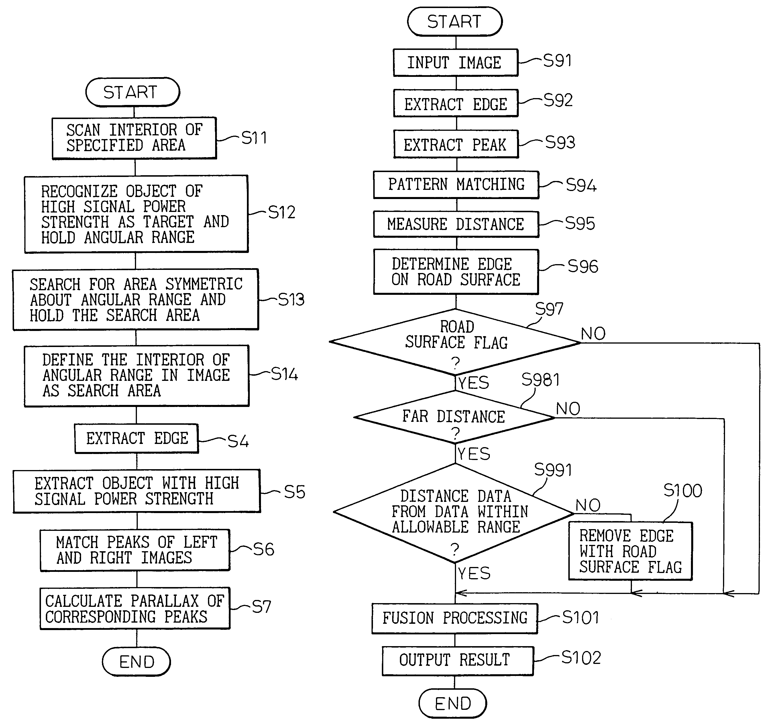
[0061]In FIG. 8, the interior of a specified area is scanned by the EHF radar 11 in step S1. FIG. 9 shows the result of scanning obtained from the EHF radar 11. In FIG. 9, the abscissa represents the horizontal position (angle) of the area scanned, and the ordinate the power strength in dB. In the case where a preceding vehicle 6 is present, as shown, the signal power strength is high at the horizontal position corresponding to the preceding vehicle 6.
[0062]In step S2, an object having a high signal power strength (not less than P dB) is recognized as a target, and the range (X0 to X1) where the target is present is held as a search area. In the case shown in FIG. 3, what is detected as a target is the preceding vehicle 6 alone. Power is not detected from a planar object like the lines 7 drawn on the road surf...
embodiment 1-2
[0069]The detection of the search area in Step S2 of FIG. 8 can be variously modified.
[0070]FIG. 11 shows a different method of extracting the search area in step S2. FIG. 12 shows the result of this edge extraction. In FIG. 11, the range of first level P0 to second level P1 dB of the signal power strength obtained from the EHF radar 11 is defined as a predetermined level range of power strength, and the ranges X0 to X1, X2 to X3 in the particular level range are extracted as a search area. The portion of FIG. 11 where the power strength is high represents the detection of a target. The range of P0 to P1 dB where the signal power strength changes sharply represents the edge position of the target. According to this embodiment, therefore, the position where the edges can probably be extracted can be further limited, and therefore, as shown in FIG. 12, only the edges of the target can be extracted, thereby further shortening the processing time.
PUM
 Abstract
Description
Claims
Application Information
 - R&D
- Intellectual Property
- Life Sciences
- Materials
- Tech Scout
- Unparalleled Data Quality
- Higher Quality Content
- 60% Fewer Hallucinations
Browse by: Latest US Patents, China's latest patents, Technical Efficacy Thesaurus, Application Domain, Technology Topic, Popular Technical Reports.
© 2025 PatSnap. All rights reserved.Legal|Privacy policy|Modern Slavery Act Transparency Statement|Sitemap|About US| Contact US: help@patsnap.com


