Transmission apparatus, transmission control program, and transmission method

a technology of transmission apparatus and control program, applied in the direction of coding, channel coding adaptation, code conversion, etc., can solve the problems of transmission increase, difficulty in estimating communication traffic between other terminals, and above-mentioned techniques may not be able to cope with congestion, so as to control congestion in the transmission line

Active Publication Date: 2008-05-20
FUJITSU LTD
View PDF29 Cites 49 Cited by
  • Summary
  • Abstract
  • Description
  • Claims
  • Application Information

AI Technical Summary

Benefits of technology

[0025]Therefore, according to the present invention, it is possible to provide a technique for, in the event that a packet loss has occurred on a transmission line, compensating for the loss efficiently.
[0034]According to the invention as described above, an excellent technique for, in the event that a loss has occurred with respect to a packet sent into a transmission line, compensating for the loss efficiently is provided. In addition, the present invention can also provide a technique for controlling transmission line congestion caused by retransmitting data compensating for a packet.

Problems solved by technology

However, in those techniques, for example, there are problems as described below.
However in the best-effort transmission line environment in which plural terminals are interconnected, it is difficult to estimate communication traffic between other terminals.
Therefore, the above techniques may not be able to cope with congestion that occurs suddenly.
In addition, in the case where the FEC system and the ARQ system are combined, there is a problem in that transmission increases due to retransmission, which adversely affects other communication traffic.
In particular, when congestion occurs, the packet loss occurs in a burst-like manner.
As a result, the state of a transmission line is further deteriorated.
Therefore, with this technique, a retransmitted packet may be lost and the recovery effect of the ARQ may consequently not be exhibited.

Method used


Image

  • Transmission apparatus, transmission control program, and transmission method
  • Transmission apparatus, transmission control program, and transmission method
  • Transmission apparatus, transmission control program, and transmission method

Examples


Embodiment Construction

[0044]A best mode for carrying out the invention will be hereinafter explained with reference to the drawings.

[0045]Constitutions of embodiments to be described below are examples, and the invention is not limited to the constitutions of the embodiments.

[0046]

[0047]A functional structure of a transmission apparatus of the invention will be explained with reference to the drawings.

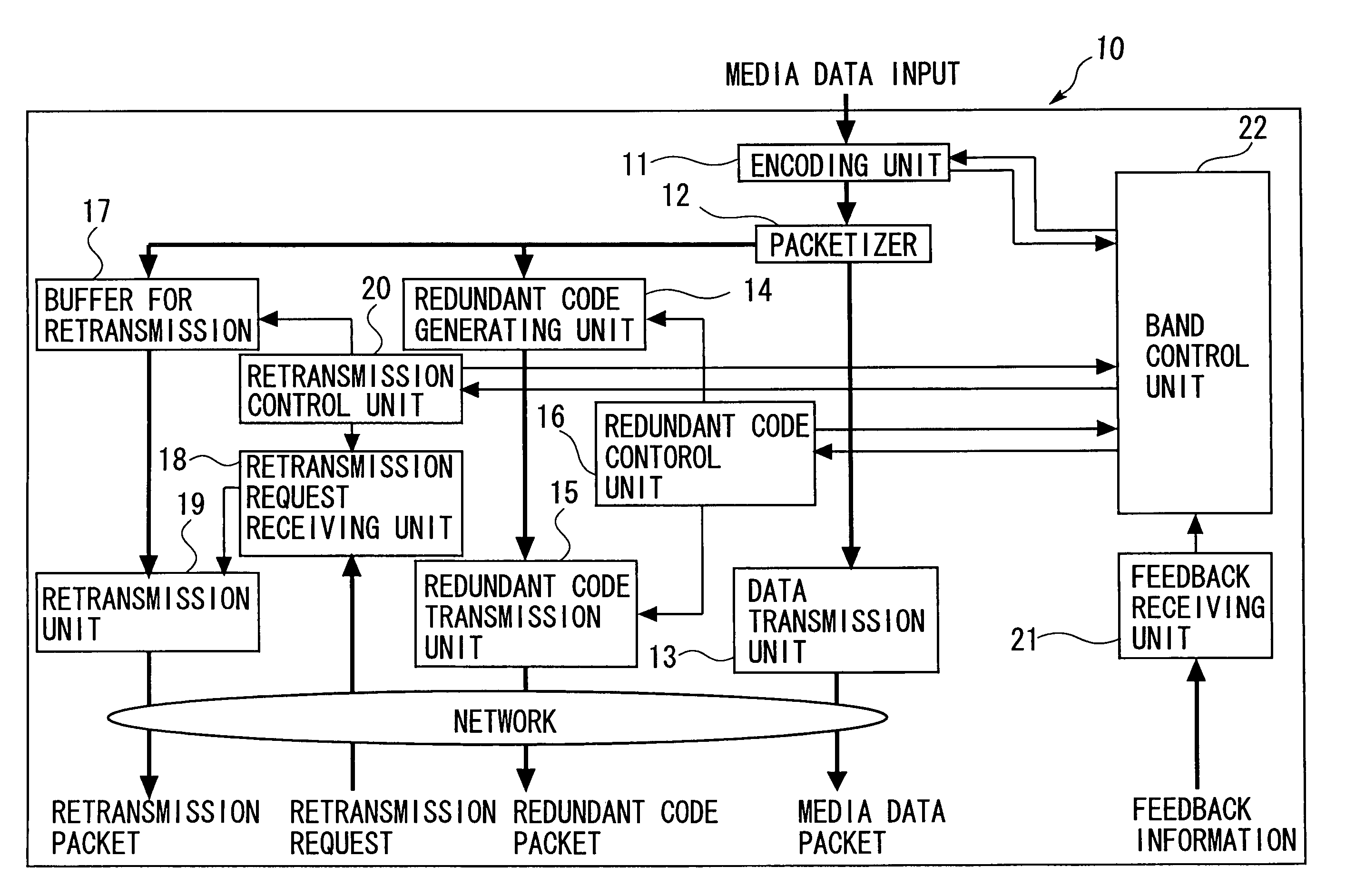
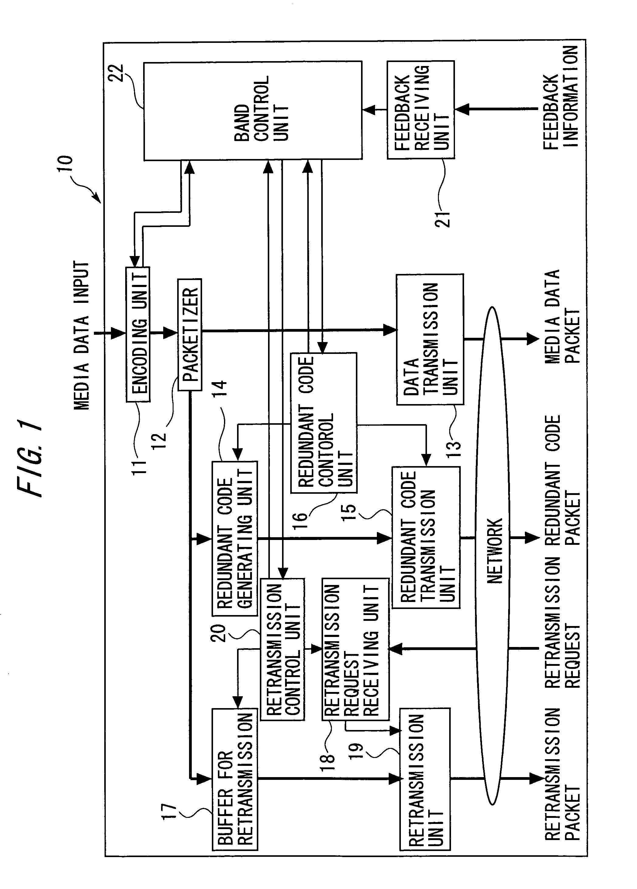
[0048]FIG. 1 is a block diagram illustrating a functional structure of the transmission apparatus of the invention. A transmission apparatus 10 of the invention encodes data such as inputted streaming information (hereinafter also referred to as media data). Thereafter, the transmission apparatus 10 packetizes the encoded media data. Then, the transmission apparatus 10 transmits the packetized media data (packet data) into a network. This transmitted packet data is received by a terminal desiring to obtain this data. In addition, in the even that a loss has occurred in the sent media data, the transmission ...


PUM


Abstract

A transmission apparatus includes a communication unit for performing transmission and reception of encoded data packets with other terminals, a redundant code generating unit for generating a redundant code packet for restoring data lost due to the loss of a data packet, a redundant code control unit for controlling the band used by the redundant code packet, a buffer for accumulating retransmission packets that can be retransmitted when corresponding data are lost, a retrieval unit for retrieving a corresponding retransmission packet from the buffer for retransmission upon receiving a retransmission request for the data packet, a retransmission control unit for controlling the band used for retransmission, and a band control unit for controlling the bandwidth of a redundant code based on the band used for retransmission and the band currently used for the redundant code.

Description

BACKGROUND OF THE INVENTION[0001]The invention relates to a method and apparatus for transmitting encoded media data.[0002]Conventionally, in a best-effort transmission line environment such as the Internet, a large volume of encoded packet data (media data) such as streaming information or video telephony is transmitted continuously.[0003]In the best-effort transmission line environment as described above, congestion occurs due to an increase in communication traffic in the network. Quality of media data being transmitted deteriorates noticeably due to this congestion. Techniques for preventing such deterioration in quality of media data include techniques as described below.[0004]One technique, for example, is to use a redundant code such as a Forward Error Correction (FEC) code. Another technique is to use retransmissions such as in an Automatic Repeat Request (ARQ) protocol.[0005]In a FEC system, parity information of the media data is generated and sent from a transmission side...

Claims


Application Information

Patent Timeline
Patent Type & Authority Patents(United States)
IPC IPC(8): H03M13/35H04L1/16H03M13/00H04L1/00H03M13/27H03M13/37H04L1/18
CPCH03M13/2707H03M13/373H04L1/0009H04L1/1809H04L1/0026H04L1/1671H04L1/18H04L1/00
Inventor ICHIKI, ATSUSHINAKAGAWA, AKIRA
Owner FUJITSU LTD
Why Eureka
Try Eureka