Radiographic apparatus that removes time lag by recursive computation

a radiographic and time-lag-removing technology, applied in the field of radiographic equipment, can solve the problems of fpd causing time lags whose adverse influence appears in x-ray images, blurring dynamic images, and inability to avoid artifacts, so as to eliminate the time lags of radiation detecting signals and remove complex detecting distortions from output images

Active Publication Date: 2008-05-27
SHIMADZU CORP
View PDF10 Cites 6 Cited by
  • Summary
  • Abstract
  • Description
  • Claims
  • Application Information

AI Technical Summary

Benefits of technology

[0046]Where a flat panel X-ray detector is used, the time lag removing device eliminates the time lags of the radiation detecting signals caused by the flat panel X-ray detector. It is also possible to remove complicated detecting distortions from output images.

Problems solved by technology

However, the FPD has a drawback of causing time lags whose adverse influence appears in X-ray images.
This results in an inconvenience such as blurring of dynamic images.
However, the only result obtained is that the above technique cannot avoid artifacts due to the time lag and satisfactory X-ray images cannot be obtained.
It has been found, however, that it is impossible for one exponential function to approximate the time lag of the FPD, and the time lag of the FPD is not eliminated by this technique, either (see U.S. Pat. No. 5,517,544).

Method used


Image

  • Radiographic apparatus that removes time lag by recursive computation
  • Radiographic apparatus that removes time lag by recursive computation
  • Radiographic apparatus that removes time lag by recursive computation

Examples


first embodiment

[0058]FIG. 2 is a block diagram showing an overall construction of a fluoroscopic apparatus in a first embodiment.

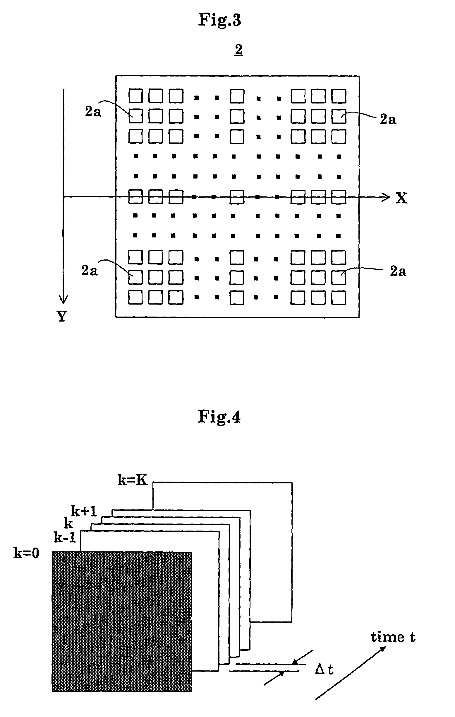
[0059]As shown in FIG. 2, the fluoroscopic apparatus includes an X-ray tube (radiation emitting device) 1 for emitting X rays toward a patient M, an FPD (radiation detecting device) 2 for detecting X rays transmitted through the patient M, an analog-to-digital converter (signal sampling device) 3 for digitizing X-ray detection signals (radiation detection signals) taken from the FPD (flat panel X-ray detector) 2 at predetermined sampling time intervals Δt, a detection signal processor 4 for creating X-ray images based on X-ray detection signals outputted from the analog-to-digital converter 3, and an image monitor 5 for displaying the X-ray images created by the detection signal processor 4. That is, the apparatus is constructed to acquire X-ray images from the X-ray detection signals taken from the FPD 2 by the analog-to-digital converter 3 as the patient M is irradiate...

second embodiment

[0090]In the second embodiment, the time lag remover 11 computes the lag-free X-ray detection signals Xk corresponding to the X-ray detection signals Yk for one X-ray image, and the detection signal processor 4 creates X-ray images, both at each period between the sampling time intervals Δt (= 1 / 30 second).

[0091]This embodiment has the same construction and function as the first embodiment except that the apparatus is constructed for creating X-ray images one after another in real time at a rate of about 30 images per second, and displaying the created X-ray images continuously in real time. The features common to the first embodiment will not be described, and description will be made on what is different from the first embodiment.

[0092]An operation for performing X-ray radiography with the apparatus in the second embodiment will be described with reference to the drawings.

[0093]FIG. 7 is a flow chart showing a procedure of X-ray radiography in the second embodiment.

[0094][Step R1]...


PUM

PropertyMeasurementUnit
attenuation time constantsaaaaaaaaaa
time constantsaaaaaaaaaa
attenuation time constantaaaaaaaaaa

Abstract

A radiographic apparatus obtains lag-free radiation detection signals with lag-behind parts removed from radiation detection signals taken from a flat panel X-ray detector as X rays are emitted from an X-ray tube. The lag-behind parts are removed by a recursive computation on an assumption that the lag-behind part included in each X-ray detection signal is due to an impulse response formed of exponential functions, N in number, with different attenuation time constants. X-ray images are created from the lag-free radiation detection signals.

Description

BACKGROUND OF THE INVENTION[0001](1) Field of the Invention[0002]This invention relates to a radiographic apparatus for medical or industrial use, for obtaining radiographic images based on radiation detection signals fetched at predetermined sampling time intervals by a signal sampling device from a radiation detecting device as radiation is emitted from a radiation emitting device. More particularly, the invention relates to a technique for fully eliminating time lags, due to the radiation detecting device, of the radiation detection signals taken from the radiation detecting device.[0003](2) Description of the Related Art[0004]In a medical fluoroscopic apparatus which is a typical example of radiographic apparatus, a flat panel X-ray detector (hereinafter called “FPD” as appropriate) has recently been used as an X-ray detecting device for detecting X-ray penetration images of a patient resulting from X-ray emission from an X-ray tube. The FPD includes numerous semiconductor or ot...

Claims


Application Information

Patent Timeline
Patent Type & Authority Patents(United States)
IPC IPC(8): H05G1/64G01D18/00A61B6/00A61B6/02G03B42/02G06T11/00G21K1/12H04N5/32H04N5/335H04N5/357H04N5/376H04N5/378
CPCA61B6/4233G06T11/005A61B6/02G06T2211/412B29C65/601B29C65/78
Inventor OKAMURA, SHOICHIFUJII, KEIICHIADACHI, SUSUMUHIRASAWA, SHINYAYOSHIMUTA, TOSHINORITANABE, KOICHIKAINO, MASATOMOKOYAMA, HIROSHI
Owner SHIMADZU CORP
Why Eureka
Try Eureka