
Biopsy anchor device with cutter

a biopsy anchor and cutter technology, applied in the field of surgical biopsy instruments and methods, can solve the problems of increasing the likelihood of misdiagnosis of the condition, the need for biopsy, and the failure of all the desired target tissue, so as to reduce the risk of infection or other complications, avoid movement, and stop bleeding

Inactive Publication Date: 2008-05-27
SENORX
View PDF198 Cites 69 Cited by
  • Summary
  • Abstract
  • Description
  • Claims
  • Application Information

AI Technical Summary

Benefits of technology

[0025]An advantage of the present invention is that it provides a roughly spherical specimen of target tissue. A roughly spherical specimen is easily examined to detect the presence and extent of diseased tissue. If the tissue within the specimen is found to be in fact diseased, e.g. to contain a carcinoma, then the entire surface of the roughly spherical specimen should be examined to be sure that there is no diseased tissue at the specimen margins. If the margins are free of diseased tissue, then the physician can be reasonably assured that all of the diseased tissue has been removed. Alternatively, the presence of diseased tissue at the margins of the specimen suggests that additional diseased tissue may remain within the patient's body.
[0026]After removing the target tissue samples or diseased tissues, additional procedures may be performed at the biopsy site or site of diseased tissue. For example, it may be desirable to cauterize, coagulate or otherwise treat the resulting cavity to stop bleeding and reduce the risk of infection or other complications. Where tissue isolation is performed, electrosurgical coagulation may be performed before or after removing the tissue specimen from the patient. Also, it may be advantageous to mark the site for future surgical procedures should pathological tests performed on the biopsy specimen indicate surgical removal or other treatment of the suspected tissue mass from which the specimen was removed. Such marking can be performed, for example, by the apparatus and method disclosed and claimed in co-pending U.S. patent application Ser. No. 09 / 343,975, filed Jun. 30, 1999, entitled “Biopsy Site Marker and Process and Apparatus for Applying It,” which is hereby incorporated by reference in its entirety.
[0027]The devices and methods of the invention provide the advantage of anchoring the device at a target location, avoiding movement after a site of interest has been identified within the body of a patient. A further advantage is provided by the ability of the device to cut a body of tissue from that correct location, without needing to position a separate instrument at the site. In addition, the present invention provides a roughly spherical specimen of target tissue, which by its shape is easily examined to detect the presence and extent of diseased tissue.

Problems solved by technology

Tissues of interest, such as nodules, masses, tumors and the like, which are typically the desired targets of a biopsy sample, may be readily displaced, pushed aside or otherwise deformed during biopsy procedures, making it likely that some or all of the desired target tissue may be missed during the biopsy procedure, thereby increasing the likelihood of misdiagnosis of the condition that led to the need for the biopsy.
However, there is frequently a delay between the positioning of the device and the taking of the biopsy sample, so that the device or tissue may move and prevent acquisition of the desired tissue.

Method used


Image

  • Biopsy anchor device with cutter
  • Biopsy anchor device with cutter
  • Biopsy anchor device with cutter

Examples


Embodiment Construction

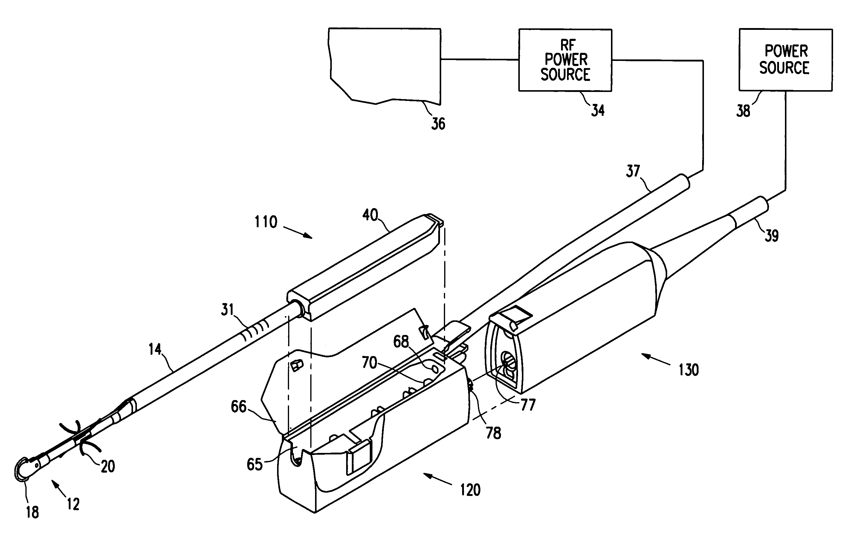
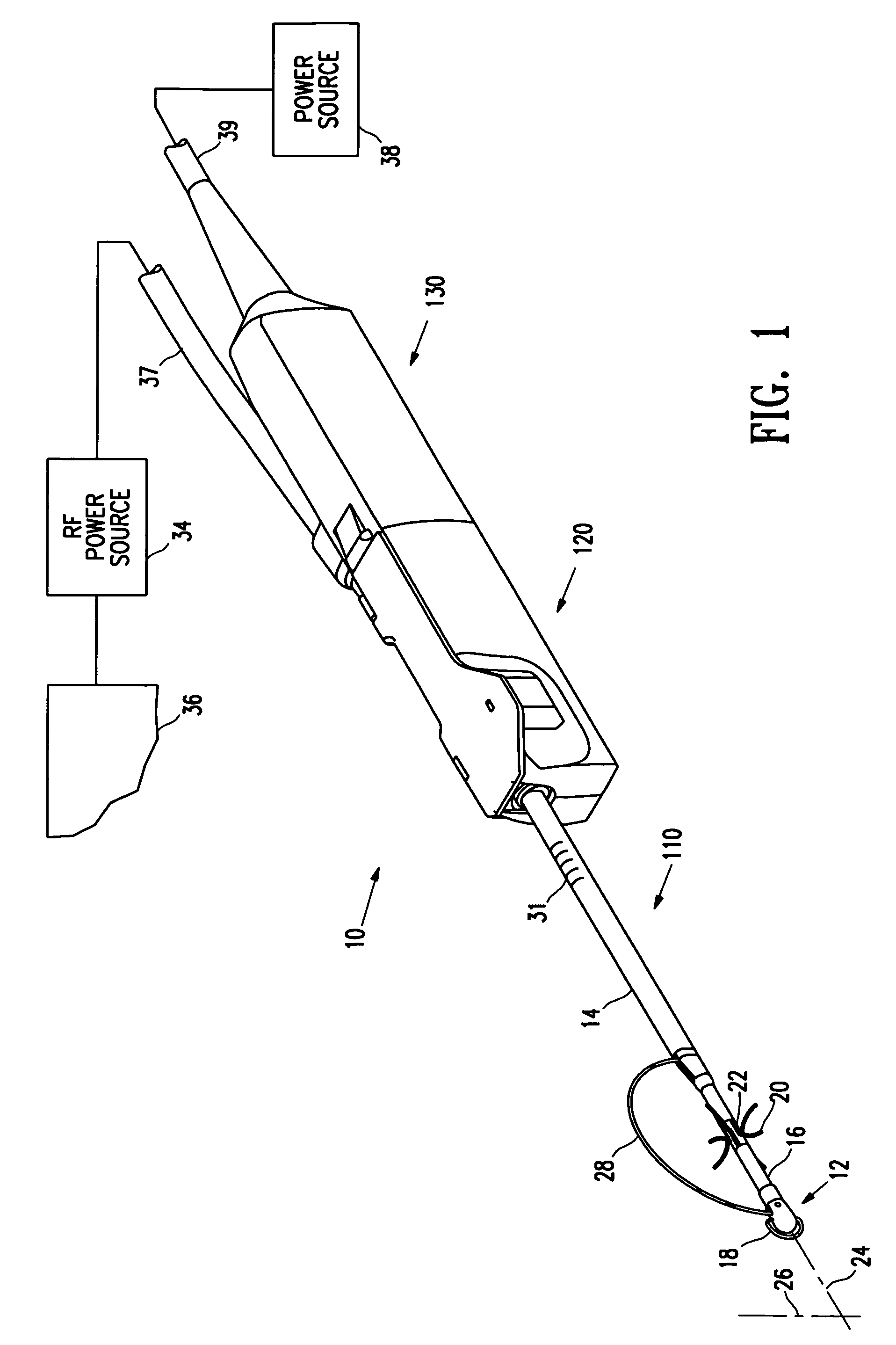
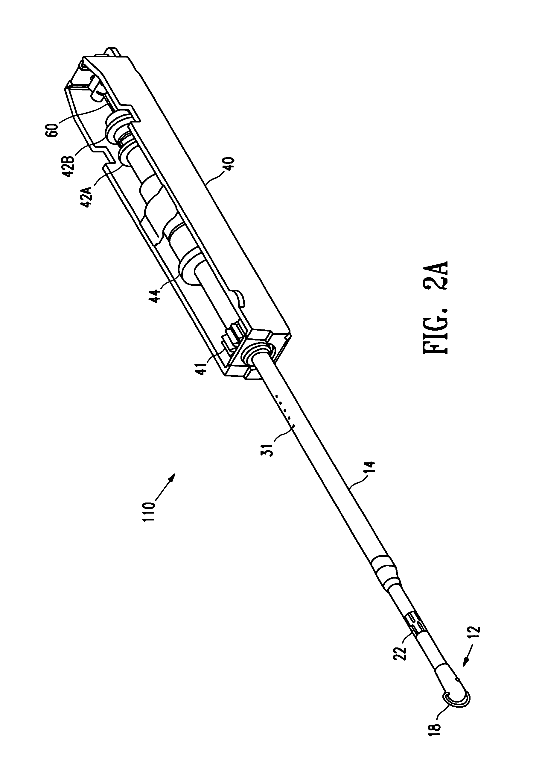
[0038]In FIG. 1 and in all succeeding figures, like elements are indicated by like numerals. Reference is made to FIG. 1, showing a system of the invention 10 comprising an electrosurgical device, or wand, 110, a surgeon's disposable unit 120, and a motor unit 130. These devices may be used to access target tissue within a patient, to isolate a body of target tissue from its supporting bed, to perform a biopsy on target tissue at a desired site within a patient, or to perform a lumpectomy on a breast of a patient. When assembled together, the devices form a system for accessing tissue within a patient's body, including, in various aspects, a biopsy system and a lumpectomy system. These systems further comprise devices for anchoring tissue that has been accessed, or for ablating tissue that has been accessed. A portion of wand 110 is illustrated in FIG. 1. The wand 110 comprises an electrosurgical device that includes a distal tip 12 situated at the distal portion 16 of a shaft 14. S...


PUM


Abstract

A device for accessing and for isolating a desired site within a patient's body, and for obtaining a body of tissue from a patient at the site that includes an electrosurgical cutting electrode near the distal tip of a shaft, an anchoring mechanism and an electrosurgical side-cutting device. Methods are provided for accessing a target site within a patient's body, anchoring a body of tissue at the site, and isolating the body of tissue at the site. The method may be performed for a surgical biopsy or lumpectomy at the target site within a patient's body.

Description

CROSS-REFERENCE TO RELATED APPLICATIONS[0001]The present invention is a continuation of U.S. patent application Ser. No. 09 / 753,529 for “Biopsy Anchor Device with Cutter,” filed on Dec. 28, 2000 now U.S. Pat. No. 6,540,695, and a continuation-in-part of U.S. patent applications Ser. No. 09 / 057,303 for “Breast Biopsy System and Method,” filed on Apr. 8, 1998, now U.S. Pat. No. 6,331,166; Ser. No. 09 / 146,185 for “Methods and Apparatus for Securing Medical Instruments to Desired Locations in a Patient's Body,” filed on Sep. 1, 1998 now U.S. Pat. No. 6,540,693; Ser. No. 09 / 159,467 for “Electrosurgical Biopsy Device and Method,” filed on Sep. 23, 1998, now U.S. Pat. No. 6,261,241; Ser. No. 09 / 238,965 for “Tissue Specimen Destruction Device and Method Thereof,” filed on Jan. 27, 1999 now U.S. Pat. No. 6,659,105; Ser. No. 09 / 356,187 for “Electrosurgical Lesion Location Device,” filed on Jul. 16, 1999, now U.S. Pat. No. 6,312,429; and Ser. No. 09 / 477,255 for “Apparatus and Method for Access...

Claims


Application Information

Patent Timeline
Patent Type & Authority Patents(United States)
IPC IPC(8): A61B10/00A61B17/14A61B17/32A61B18/18A61B10/02A61B17/00A61B17/02A61B17/22A61B17/28A61B17/34A61B18/14A61B19/00
CPCA61B10/0266A61B17/00491A61B17/32056A61B17/320725A61B18/14A61B18/1477A61B18/1482A61B19/54A61B2018/1253A61B2018/126A61B2018/1407A61B2018/1425A61B2018/144A61B2018/1475A61B2018/162A61B2018/1861A61B2019/5408A61B10/02A61B17/0218A61B17/282A61B17/3417A61B17/3439A61B18/148A61B18/1487A61B18/1492A61B19/24A61B19/5225A61B2010/0208A61B2017/320064A61B2017/320733A61B2017/3484A61B2017/3488A61B2018/00208A61B2018/00214A61B2018/00267A61B2018/00273A61B2018/00333A61B2018/00577A61B2018/00601A61B2018/00898A61B2018/0091A61B2018/00916A61B2018/1246A61B90/02A61B90/37A61B90/39A61B2090/3908
Inventor BURBANK, FREDQUICK, RICHARD L.SHABAZ, MARTIN V.LUBOCK, PAULJONES, MICHAEL L.
Owner SENORX
Learn More