
FDB motor with tapered shaft for improved pumping efficiency

a technology of fdb motors and shafts, applied in the direction of positive displacement liquid engines, pumping, machines/engines, etc., can solve the problems of premature drive failure, wear in components, and the relatively rotating components may contact each other, so as to increase the pumping efficiency of fluid dynamic bearings.

Inactive Publication Date: 2008-05-27
SEAGATE TECH LLC
View PDF6 Cites 25 Cited by
  • Summary
  • Abstract
  • Description
  • Claims
  • Application Information

AI Technical Summary

Benefits of technology

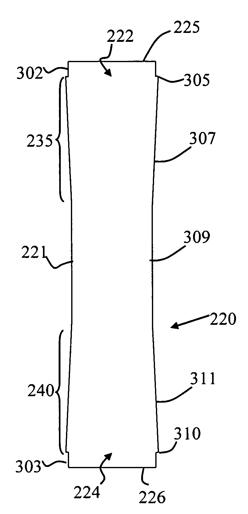
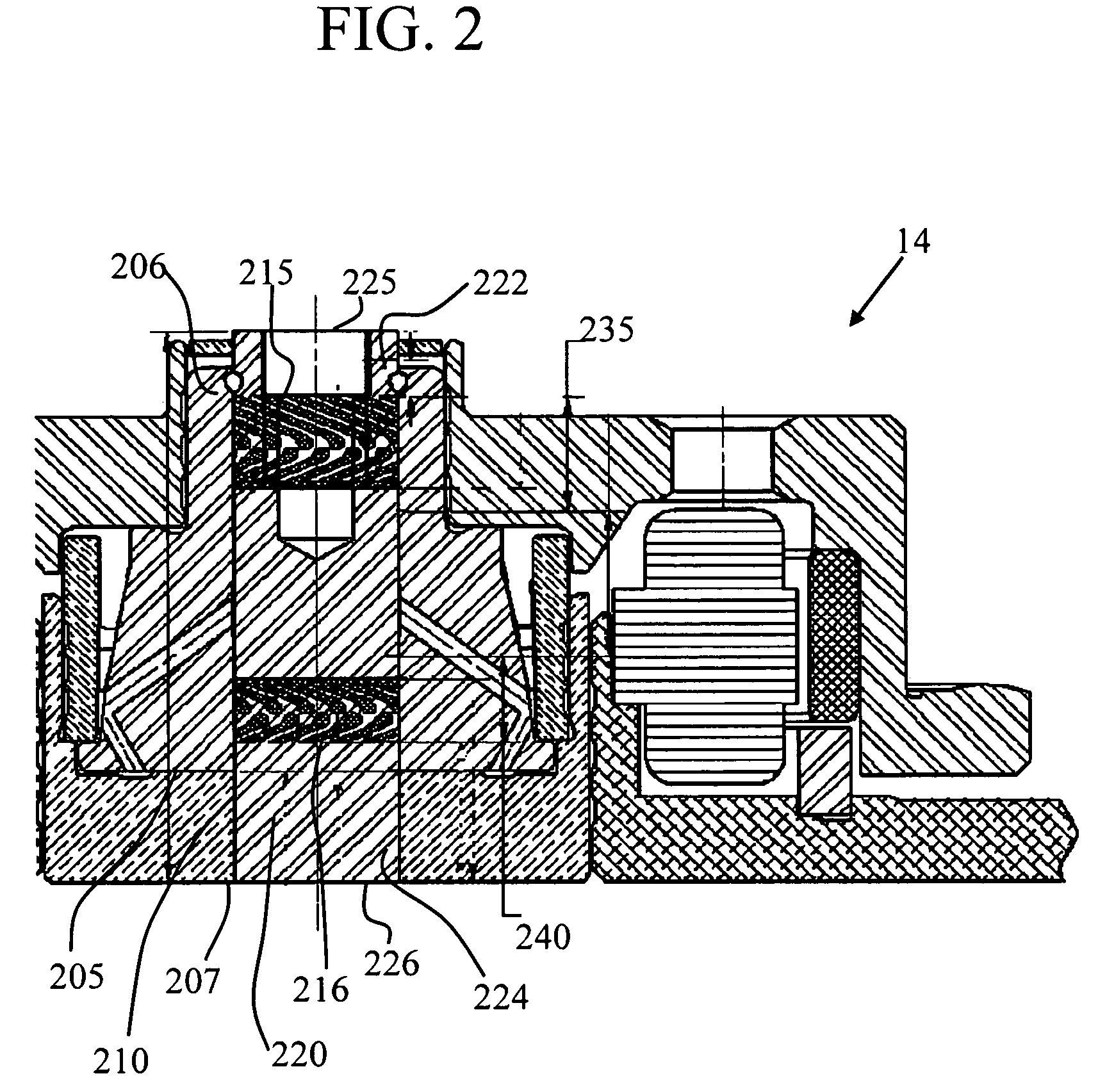
"The patent describes a shaft for an FDB motor that has a coating on its outer surface. The coating is applied in two stages, with the first stage tapering towards the first end and the second stage tapering towards the second end. This coating helps to increase the efficiency of the motor. The shaft is tapered from relatively wide diameters at the ends to a narrower diameter in the middle. The coating can be a wear-resistant coating, such as a DLC coating or ceramic coating. The method for applying the coating involves providing coating material at the ends of the shaft and directing it towards the outer surface of the shaft. The motor also includes a bearing sleeve with grooves on its interior surface, and the shaft is inserted into the sleeve. The shaft has a coating on its outer surface, which tapers in thickness from the ends to the middle. This design improves the performance of the motor."

Problems solved by technology

Grooved regions may tend to evacuate lubricating liquid from a portion of the journal, and therefore there is some danger that the relatively rotating components may contact each other if jolted or jarred during operation (op shock event).
That contact may induce wear in the components and may increase risk of premature drive failure.

Method used


Image

  • FDB motor with tapered shaft for improved pumping efficiency
  • FDB motor with tapered shaft for improved pumping efficiency
  • FDB motor with tapered shaft for improved pumping efficiency

Examples


Embodiment Construction

[0017]The following description is presented to enable a person of ordinary skill in the art to make and use various aspects of the inventions. Descriptions of specific materials, techniques, and applications are provided only as examples. Various modifications to the examples described herein will be readily apparent to those skilled in the art, and the general principles defined herein may be applied to other examples and applications without departing from the spirit and scope of the inventions. For example, aspects and examples may be employed in a variety of motors, including motors for use in disc storage drives. Motors for disc storage drives may be designed and may operate in a number of ways. Exemplary subject matter provided herein is for illustrating various inventive aspects and is not intended to limit the range of motors and devices in which in such subject matter may be applied.

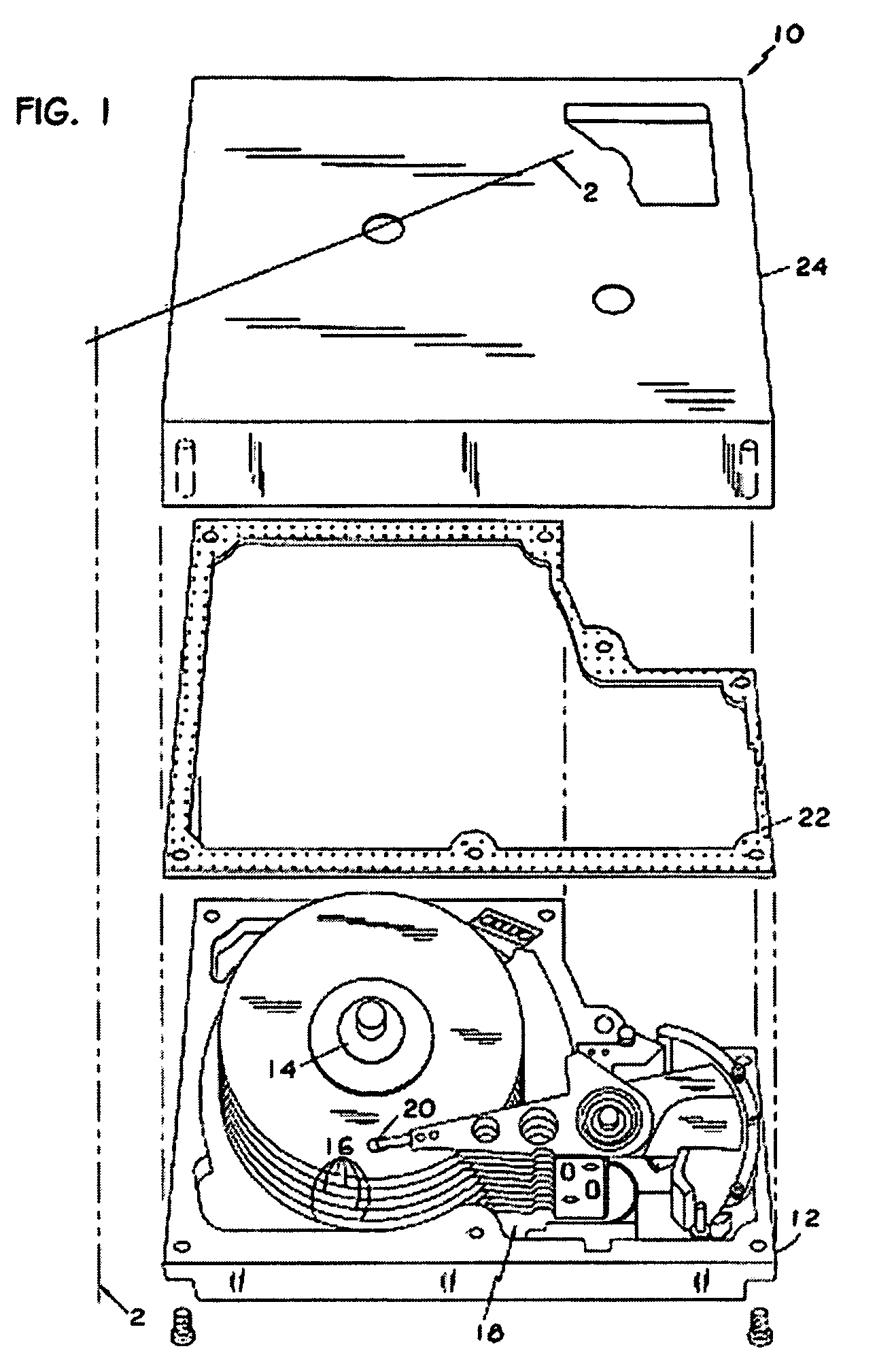
[0018]Turning briefly to FIG. 1, a plan view of an exemplary magnetic disc drive storage sy...


PUM


Abstract

For motors having a journal with one or more groove regions and a shaft for relative rotation in the journal, aspects include providing a dual tapered shaft. The shaft may be tapered by the application of a wear resistant coating at least opposite the groove regions. The coating introduces a shaft taper from near a top end and from near a bottom end towards the shaft middle. The shaft taper may provide for improved pumping efficiency. The coating may be applied in various processes such as chemical vapor deposition or physical vapor deposition to establish a thickness gradient of coating material from near the top end and near the bottom end towards the shaft middle. In one example, the coating includes a DLC coating. Additionally, shaft portions may be shielded to prevent coatings thereon.

Description

RELATED APPLICATION[0001]This application is related to and claims benefit of priority from U.S. Provisional Patent Application No. 60 / 554,961, filed on Mar. 19, 2004, and which is fully incorporated by reference herein as if fully set forth herein.BACKGROUND[0002]The present invention relates to grooved regions, such as pumping seal regions, in Fluid Dynamic Bearing (FDB) motors, and more particularly to increasing pumping efficiency and / or reducing component wear near grooved regions of FDB motors.DESCRIPTION OF RELATED ART[0003]Groove regions, such as grooved pumping seal regions, have been used in FDB motors. Some such FDB motors have a predominantly straight journal bearing formed by opposing inner and outer surfaces of relatively rotating components. By example, a journal bearing may be formed between an inner surface of a bearing sleeve and an outer surface of a shaft. Such journal bearings are designed to maintain a gap between the inner and outer surfaces. Lubricating liqui...

Claims


Application Information

Patent Timeline
Patent Type & Authority Patents(United States)
IPC IPC(8): H02K5/16F04B17/00F04B35/04F16C3/02F16C33/10H02K7/08H02K15/14
CPCF16C3/02F16C33/107H02K5/1677F16C2370/12B64C31/036B64D17/30
Inventor LEBLANC, JEFFRY A.HERNDON, TROY M.AMEEN, MOHAMMAD M.KHAN, RAQUIB U.
Owner SEAGATE TECH LLC
Learn More