Optical MEMS wavefront diagnostic transceivers and receiver

a technology of optical path and receiver, applied in the direction of optical apparatus testing, optical radiation measurement, instruments, etc., can solve the problems of preventing the use of permanent testing instruments for remote or automated functions, too large current instruments to probe optical paths, and inconvenient us

Inactive Publication Date: 2008-05-27
THE BOEING CO
View PDF9 Cites 19 Cited by
  • Summary
  • Abstract
  • Description
  • Claims
  • Application Information

AI Technical Summary

Problems solved by technology

Current instruments to probe optical paths are too large for use in many applications.
Similarly, current instruments are too heavy to be used as permanent fixtures in many applications such as many airborne applications, thus, preventing the use of permanent testing instruments for remote or automated functionalities.
Rather, current systems require temporary installation for inspection by very experienced hands-on individuals.
The installation and removal of the inspection system from an optical system could misalign or damage the optical system.
These restrictions on use of current instruments for testing optical paths limits the ability to test and limiting the quality control of many optical systems.

Method used


Image

  • Optical MEMS wavefront diagnostic transceivers and receiver
  • Optical MEMS wavefront diagnostic transceivers and receiver
  • Optical MEMS wavefront diagnostic transceivers and receiver

Examples


Embodiment Construction

[0019]The present inventions now will be described more fully hereinafter with reference to the accompanying drawings, in which some, but not all embodiments of the invention are shown. Indeed, these inventions may be embodied in many different forms and should not be construed as limited to the embodiments set forth herein; rather, these embodiments are provided so that this disclosure will satisfy applicable legal requirements. Like numbers and variables refer to like elements and parameters throughout.

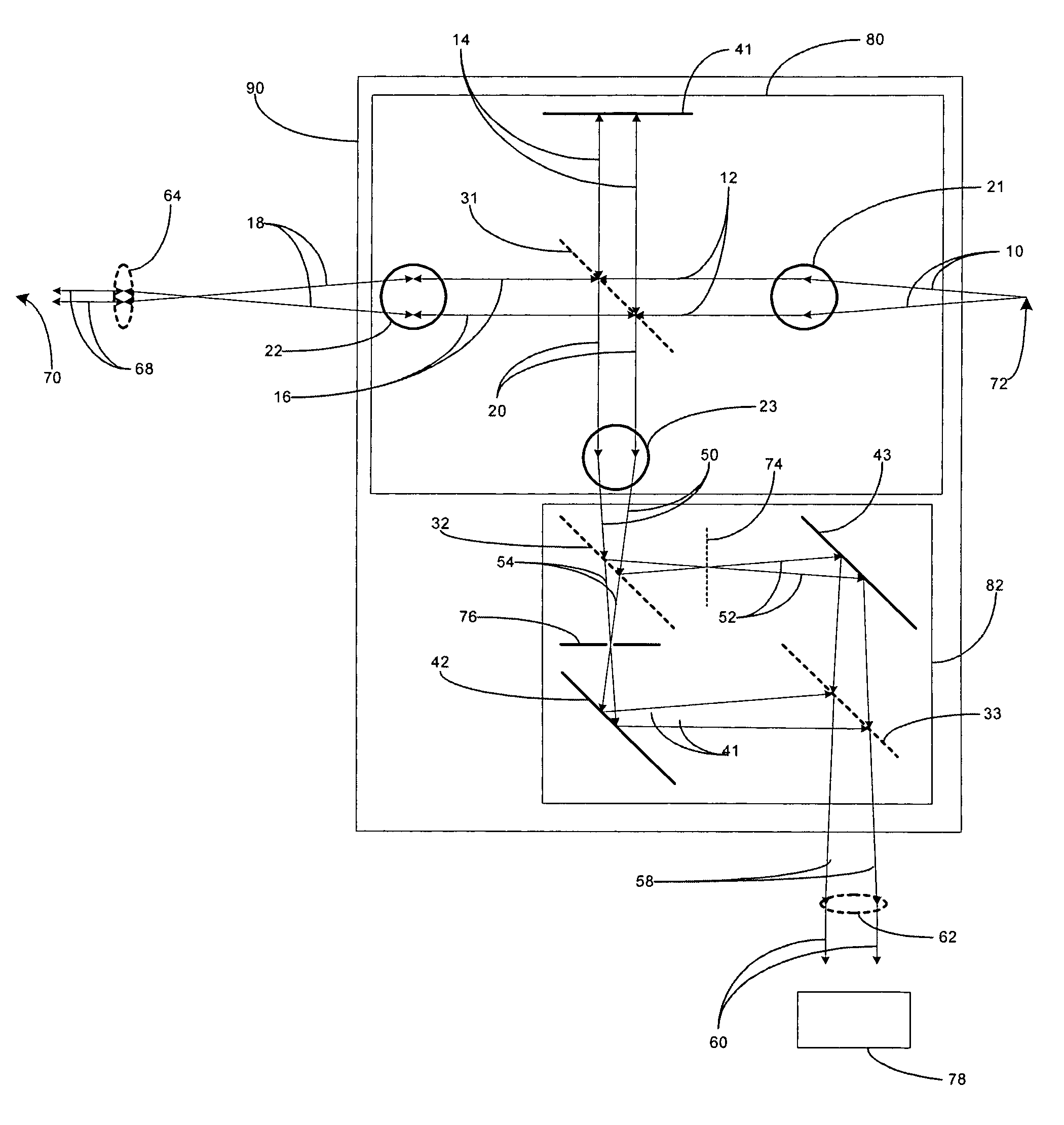
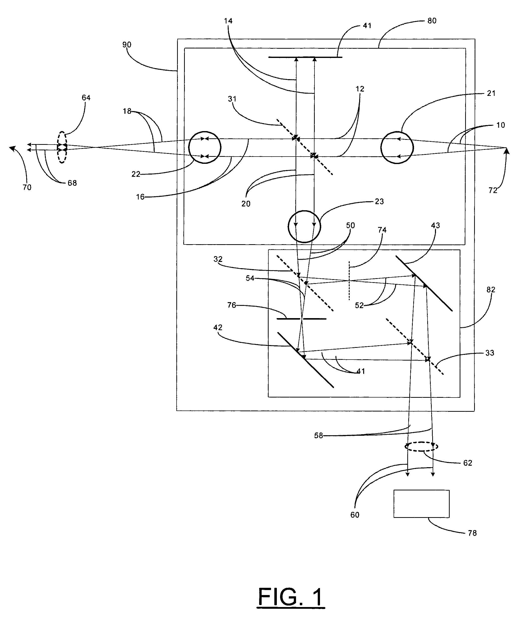
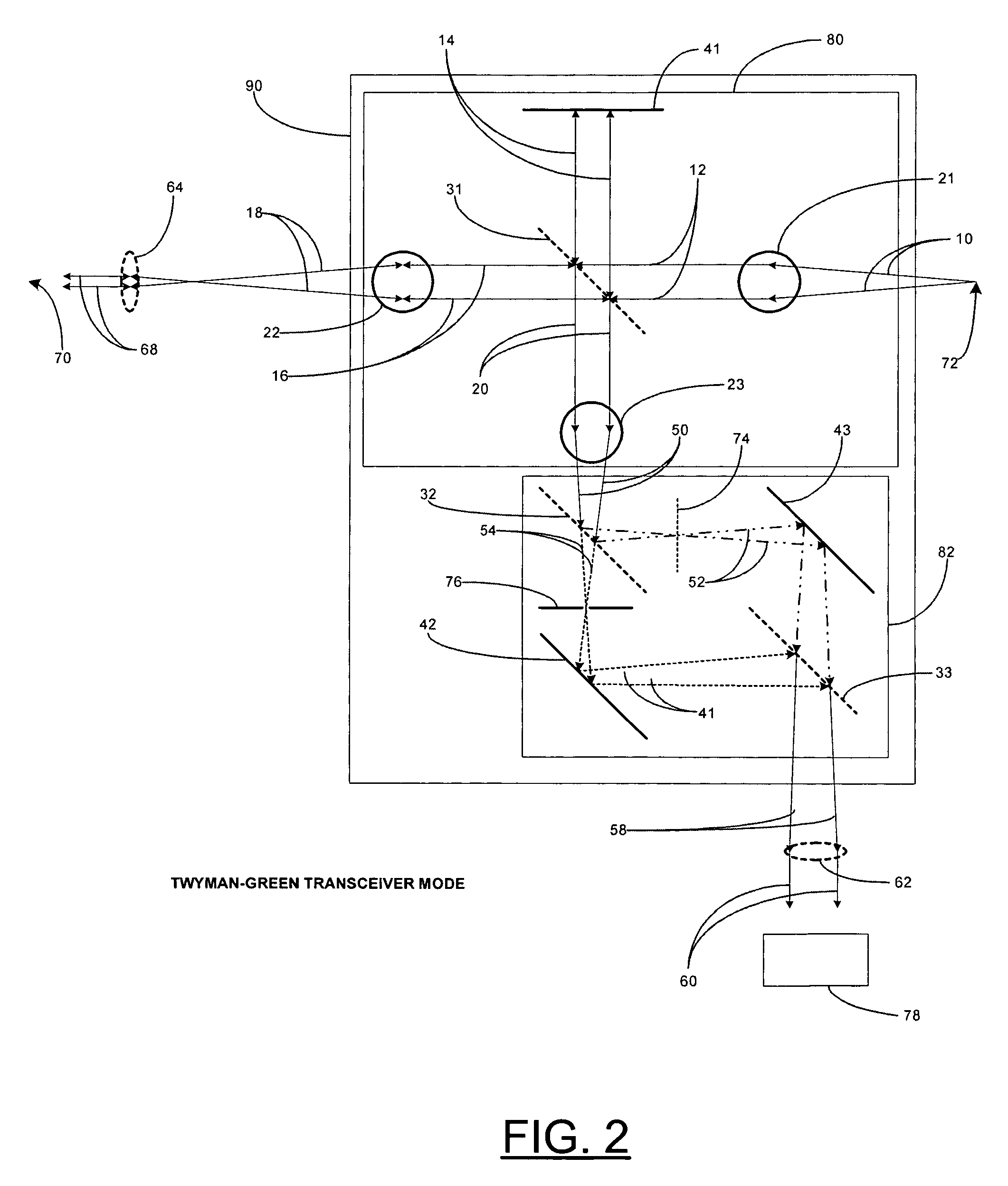
[0020]Embodiments of the present invention are described with reference to three modes of operation: Twyman-Green transceiver mode, Mach-Zehnder transceiver mode, and Mach-Zehnder receiver mode. FIG. 1 is a schematic diagram showing all of the various operations of each of the three modes of operation. FIGS. 2, 3, and 4, are particular examples of each of the modes of operation. FIG. 2 is an example of Twyman-Green transceiver mode. FIG. 3 is an example of Mach-Zehnder transceiver m...


PUM


Abstract

A combination interferometer (ifo) inspection device is provided which includes a Twyman-Green (T-G) ifo optically coupled to a Mach-Zehnder (M-Z) ifo. MEMS and MOEMS versions permit substantial reduction in size and weight to permit permanently embedding an inspection device into an optical system which permits remote and automated inspection and / or adjustment of the optical system. The inspection device permits use of different coherence length light sources and receipt of an output signal from an optical system. The addition of the T-G ifo to the M-Z ifo aids pinhole alignment and general alignment to the optical system under test, as well as inspection with long coherence sources, while the addition of the M-Z ifo permits measurement with long or short coherence sources, allows measurement of the output beam, and permits the system to operate in a receive-only mode with an external source. The inspection device provides versatile functionality and redundancy for using a single inspection device in a variety of situations and manners in the same application.

Description

FEDERALLY SPONSORED RESEARCH OR DEVELOPMENT[0001]This invention was made with support of the United States Government under contract number F29601-97-C-001 awarded by the U.S. Air Force. The United States Government may have certain rights in the subject matter of this invention.FIELD OF THE INVENTION[0002]The present invention relates generally to an apparatus and method for inspecting an optical path or component or surface and, more particularly, to an apparatus and method for inspecting an optical path or component or surface using a combination Twyman-Green-Mach-Zehnder interferometer.BACKGROUND[0003]Optical systems can require quality control to ensure proper alignment and determine aberrations of the optical path of an optical system. An optical path carries light radiation from a source, typically a laser source, to an output device. And in going from the source to the output device, the radiation impinges upon and passes through mirrors and beam splitters and often passes t...

Claims


Application Information

Patent Timeline
Patent Type & Authority Patents(United States)
IPC IPC(8): G01B11/00
CPCG01J9/02G01M11/0221G01M11/0271G01B9/02051G01B9/02065
Inventor BROOKS, LAWRENCE D.
Owner THE BOEING CO
Why Eureka
Try Eureka