
Fast frequency adjustment method for synchronizing network clocks

a network clock and frequency adjustment technology, applied in the field of industrial controllers, can solve the problems of variable drift in relative time, clocks will tend to drift apart, and the speed of communication on the high-speed network is not fast enough to properly synchronize operations, and achieve the effect of avoiding jumps in time values

Active Publication Date: 2008-05-27
ROCKWELL AUTOMATION TECH
View PDF21 Cites 25 Cited by
  • Summary
  • Abstract
  • Description
  • Claims
  • Application Information

AI Technical Summary

Benefits of technology

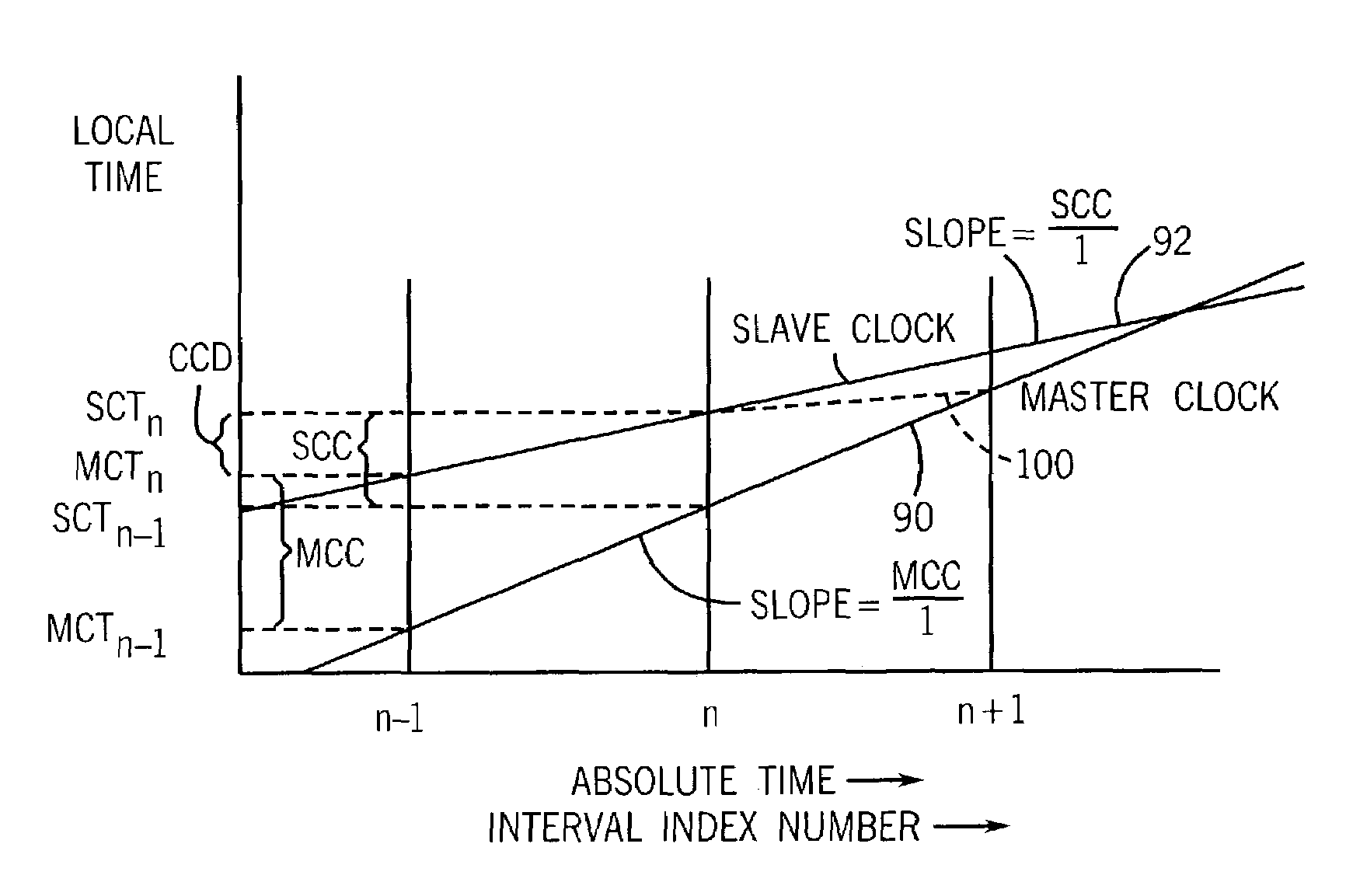
[0008]The present invention provides a method of precisely synchronizing clocks on a network using a simple calculation that corrects relative errors in time and frequency in as little as one cycle of the synchronization process. The correction operates on clock frequency and thus eliminates jumps in time values.
[0009]Specifically, the present invention provides a method of synchronizing clocks in separate nodes on a communication network starting with the step of determining a count rate of a master clock in a master node and a count rate of a slave clock in a slave node. The difference between the time values of the master clock and slave clock are then determined at a given point in time. The rate of the slave clock is adjusted based on the count rates of the master and slave clocks and on the difference in their clock values to cause the count rates and the counts of the master clock and slave clock to converge.
[0010]Thus, it is one object of the invention to use a measurement of relative count rates, not just a measurement of time value difference, to provide improved control over the convergence of two clocks.
[0012]Thus, it is another object of the invention to provide a rapid convergence of the clocks on a network. This rapid convergence provides a predictable locking of the frequencies and times of the clock regardless of their initial conditions and provides close tracking between the clocks limited only by the length of the intervals.
[0015]Thus, it is another object of the invention to provide a simple calculation for synchronizing clocks that may be implemented in firmware or software at high speed.

Problems solved by technology

For many applications, the speed of communication on the high-speed network is not sufficiently fast to properly synchronize operations at the various components of the industrial controller.
Such local clocks will tend to drift apart over time either due to minute differences in the natural frequencies of the crystal oscillators in the clocks which causes a steady drift in relative time between the clocks, or because of differences in operating conditions such as temperature, mechanical shock, and aging which causes a variable drift in relative time between the clocks.
Particularly for nondeterministic networks, such as Ethernet, efforts to synchronize clocks using network communications are hampered by the unknown delays that will be introduced by the networks.
Tight synchronization, necessary to avoid large corrective jumps in the relative time of local clocks, may require frequent synchronization signals that may adversely affect the available network bandwidth.

Method used


Image

  • Fast frequency adjustment method for synchronizing network clocks
  • Fast frequency adjustment method for synchronizing network clocks
  • Fast frequency adjustment method for synchronizing network clocks

Examples


Embodiment Construction

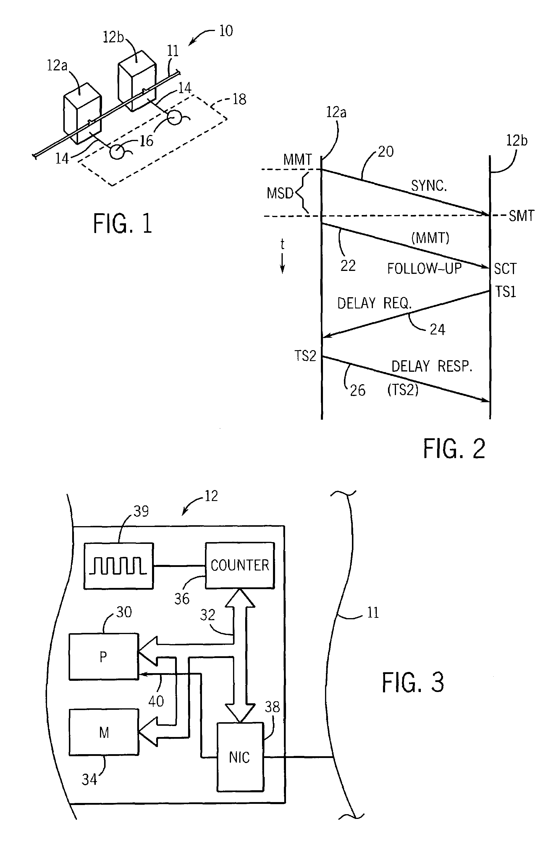
[0031]Referring now to FIG. 1, an industrial controller 10 may include a communication network 11, such as Ethernet, connecting a first node 12a and a second node 12b, both being components of an industrial controller. Each node 12 may also provide at least one input or output line 14 communicating with a sensor or actuator 16 in turn connected to the industrial process 18 as is understood in the art.

[0032]Each of the nodes 12 may include a clock (as will be described below) providing for a local time. One clock is designated a master clock and other slave clocks are synchronized to the master clock over the network 11.

[0033]Referring now to FIG. 2, each of the nodes 12 may send and receive time synchronization messages defined by IEEE standard 1588 hereby incorporated by reference. Following this protocol, a master node 12a may send a synchronization message 20 to the slave node 12b followed by a follow-up message 22 sending a value of the local time at the master node 12 at which ...


PUM


Abstract

A method of precisely synchronizing clocks held in separate nodes on a communication network is provided that adjusts clock frequency based on a measure of relative clock rates and absolute clock offsets. In one embodiment, clock convergence is obtained with one synchronization session.

Description

CROSS-REFERENCE TO RELATED APPLICATIONSSTATEMENT REGARDING FEDERALLY SPONSORED RESEARCH OR DEVELOPMENTBACKGROUND OF THE INVENTION[0001]The present invention relates generally to industrial controllers for the control of machines and processes and in particular, for an industrial controller whose components communicate over a network and have precisely synchronized local clocks.[0002]Industrial controllers are special purpose computers and circuitry for the control of processes and machinery, for example, in a factory or the like. The industrial controller reads inputs from sensors associated with the controlled process and, executing one or more stored programs, provides outputs to actuators associated with the controlled process according to the stored control programs and inputs received by the control programs.[0003]The process may encompass a large area and thus it is known to distribute the components of the industrial controller so that each component may be close to the parti...

Claims


Application Information

Patent Timeline
IPC IPC(8): H04J3/07H04J3/06
CPCH04J3/0667H04J3/0697
Inventor BALASUBRAMANIAN, SIVARAMHARRIS, KENDAL R.
Owner ROCKWELL AUTOMATION TECH
Learn More