Vehicle body rear structure of automobile

a rear structure and vehicle technology, applied in the direction of roofs, vehicle arrangements, transportation and packaging, etc., can solve the problems of increasing the burden on the rear side member, increasing the number of parts, increasing the weight of the vehicle body, etc., and achieves the reduction of local load concentration, simple construction, and rigidity and strength.

Inactive Publication Date: 2008-06-03
SUZUKI MOTOR CORP
View PDF9 Cites 13 Cited by
  • Summary
  • Abstract
  • Description
  • Claims
  • Application Information

AI Technical Summary

Benefits of technology

[0021]In the present invention, the load distributing member extending along the body longitudinal direction is assembled to the spare tire house so as to trail over the lower surface of the spare tire house; and the front end portion of the load distributing member is joined to the cross member, and the rear end portion thereof is joined to the back panel (located on the rear side of the cross member). Therefore, a load applied to the vehicle body rear part (for example, the load from the rear of vehicle body) can be distributed in the vehicle body rear part via the load distributing member, so that local concentration of load can be reduced. For this reason, according to the present invention, simply providing an additional load distributing member can achieve the necessary rigidity and strength, and the structure has a simple construction that does not bring about a significant increase in the number of parts and an increase in weight of vehicle body.
[0022]Also, in the present invention, the front and rear end portions of the load distributing member are connected to the rear floor panel. Therefore, by arranging the load distributing member so as extend from the spare tire house to the rear floor panel, the load from the rear of vehicle body can be distributed properly over a wide range of the vehicle body rear part via the load distributing member and the rear floor panel.
[0023]Further, in the present invention, the towing hook is installed on the load distributing member. Therefore, when a towing load is applied to the towing hook, the towing load at this time can be distributed over a wide range from the spare tire house to the rear floor panel, back panel, cross member, and rear side members, not merely to the load distributing member, so that the rigidity and strength of a towing hook attaching portion can be secured sufficiently.
[0024]Still further, in the present invention, the jack-up point is provided on the load distributing member. Therefore, a load applied to the jack-up point when jacking up can be distributed to the spare tire house, rear floor panel, cross member, back panel, and rear side members via the load distributing member. For this reason, the rigidity and strength of a jack-up point can be secured sufficiently.
[0025]Still further, in the present invention, the towing hook is also used as the jack-up point. Therefore, a load applied to the jack-up point at the time when the towing hook is jacked up by a jack can be distributed over a wide range from the spare tire house to the rear floor panel, cross member, and rear side members, not merely to the load distributing member. For this reason, the jack-up point can be secured without installing a patch for the jack-up point, and hence a simple construction that does not bring about an increase in the number of parts and an increase in weight of vehicle body can be realized.

Problems solved by technology

Therefore, the burden imposed on the rear side member is increased by extensive deformation of the spare tire house.
Therefore, in the related art, securing rigidity to such a degree as to be capable of sustaining various kinds of loads results in an increase in the number of parts due to the use of a patch etc. or an increase in the weight of vehicle body due to the increase in sheet thickness.
Therefore, there arises a problem in that if an excessive load is applied from the rear of the vehicle body, the load cannot be absorbed sufficiently.
Also, this structure is such that the load from a seat belt anchor is not at all considered.
Also, as a measure against the load from a seat belt anchor, its strength is insufficient because the structure is such that a load which pulls the center frame toward the front of vehicle body is sustained only by a part in which the center of the spare tire serves as a supporting point.
However, when the center frame moves toward the front of the vehicle body while being deformed due to a load from the rear of the vehicle body, the center frame hits the fuel tank, so that there is a fear of damaging the fuel tank.
Also, in the structure described in Japanese Patent Provisional Publication No. 2002-321642, although the load from the rear of vehicle body can be dealt with as described above, loads from the towing hook and the jack-up point cannot be dealt with because a reinforcing part is absent under the spare tire house.
Also, as measures against the load from a seat belt anchor, it is necessary to provide the back panel (vehicle rear end member) with sufficient rigidity due to the increase in sheet thickness of the back panel or the additional provision of a reinforcing member to restrain the deformation of the back panel because the configuration is such that a load which pulls the subcenter member toward the front of the vehicle body is sustained by only the back panel, which leads to an increase in weight and an increase in the number of parts.
However, as in the case of Japanese Utility Model Provisional Publication No. 62-43875, there is a fear of damaging the fuel tank.
Furthermore, this structure is inconvenient because the subcenter member is located above the spare tire and thus the spare tire can only be taken out of the lower side of a vehicle body.

Method used


Image

  • Vehicle body rear structure of automobile
  • Vehicle body rear structure of automobile
  • Vehicle body rear structure of automobile

Examples


Embodiment Construction

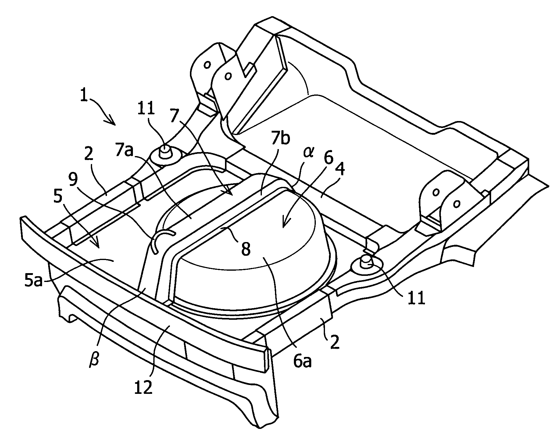
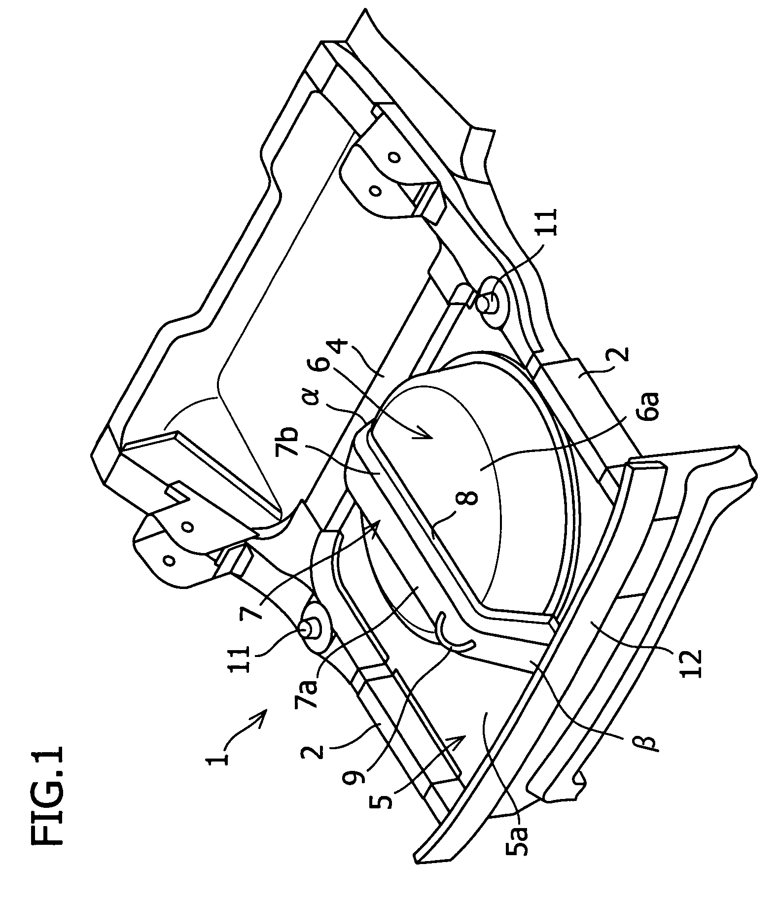
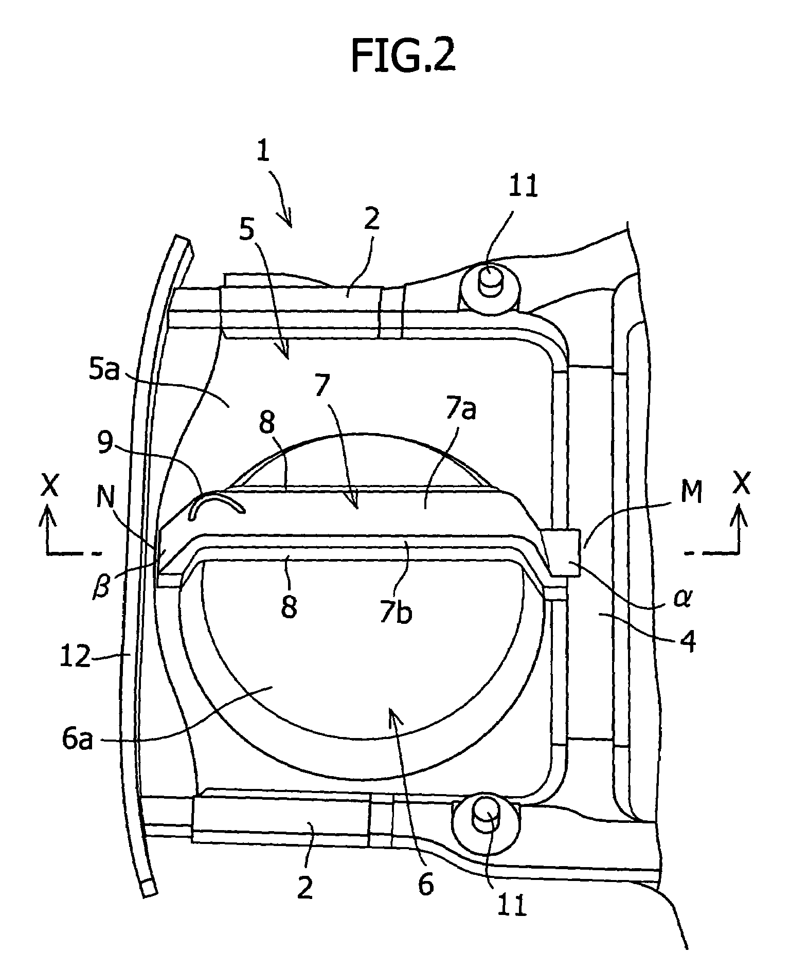
[0034]A vehicle body rear structure of an automobile in accordance with one embodiment of the present invention will now be described with reference to FIGS. 1 to 5.

[0035]FIGS. 1 and 2 are perspective views of a vehicle body rear part 1 of an automobile, which is viewed from the lower side (bottom side) of a vehicle body. As shown in FIGS. 1 and 2, between a pair of rear side members 2 extending substantially along the body longitudinal direction on both sides, right and left, of the vehicle body rear part 1, a cross member 4 is installed so as to extend substantially along the vehicle width direction at a location in front of a back panel 3 (refer to FIG. 3) disposed at the rear end of a vehicle body. A rear floor panel 5 is provided above the paired rear side members 2 and the cross member 4, and the rear floor panel 5 is provided with a spare tire house (spare tire housing) 6 consisting of a bottomed cylindrical concave portion formed by being bent at a location between the cross...


PUM


Abstract

There is provided a vehicle body rear structure of an automobile, which can deal with all of a load from a towing hook, a load from a jack-up point, a load from the rear of vehicle body, and a load from a seat belt anchor, though having a simple construction that does not bring about an increase in the number of parts and an increase in weight of vehicle body. A load distributing member 7 extending along the body longitudinal direction is assembled to a spare tire house 6 so as to trail over a lower surface 6a of the spare tire house 6; and a front end portion α of the load distributing member 7 is joined to a cross member 4, and a rear end portion β thereof is joined to the back panel 3 (located on the rear side of the cross member 4).

Description

RELATED APPLICATION[0001]This application claims priority from Japanese Patent Application No. 2004-273266; filed Sep. 21, 2004, the disclosure of which is incorporated by reference herein in its entirety.FIELD OF THE INVENTION AND RELATED ART STATEMENT[0002]The present invention relates to a vehicle body rear structure of an automobile, in which a spare tire house (spare tire housing) is provided to house a spare tire.[0003]Loads which can occur in the vicinity of a spare tire house provided in a vehicle body rear part of an automobile include a load from a towing hook, a load from a jack-up point, a load from the rear of a vehicle body, and a load from a seat belt anchor.[0004]Against these loads, there is usually no member in the vicinity of the spare tire house capable of securing rigidity and strength. Conventionally, therefore, to locally secure rigidity around the spare tire house to deal with the above-described loads, individual measures have been taken; for example, a patc...

Claims


Application Information

Patent Timeline
Patent Type & Authority Patents(United States)
IPC IPC(8): B60N99/00
CPCB62D25/2027B62D43/10
Inventor KOBAYASHI, AKIRATSUKAKOSHI, TAKANORI
Owner SUZUKI MOTOR CORP
Why Eureka
Try Eureka