
Blind spot targeting system

Inactive Publication Date: 2008-06-03
GASQUE JR SAMUEL N
View PDF11 Cites 12 Cited by
  • Summary
  • Abstract
  • Description
  • Claims
  • Application Information

AI Technical Summary

Benefits of technology

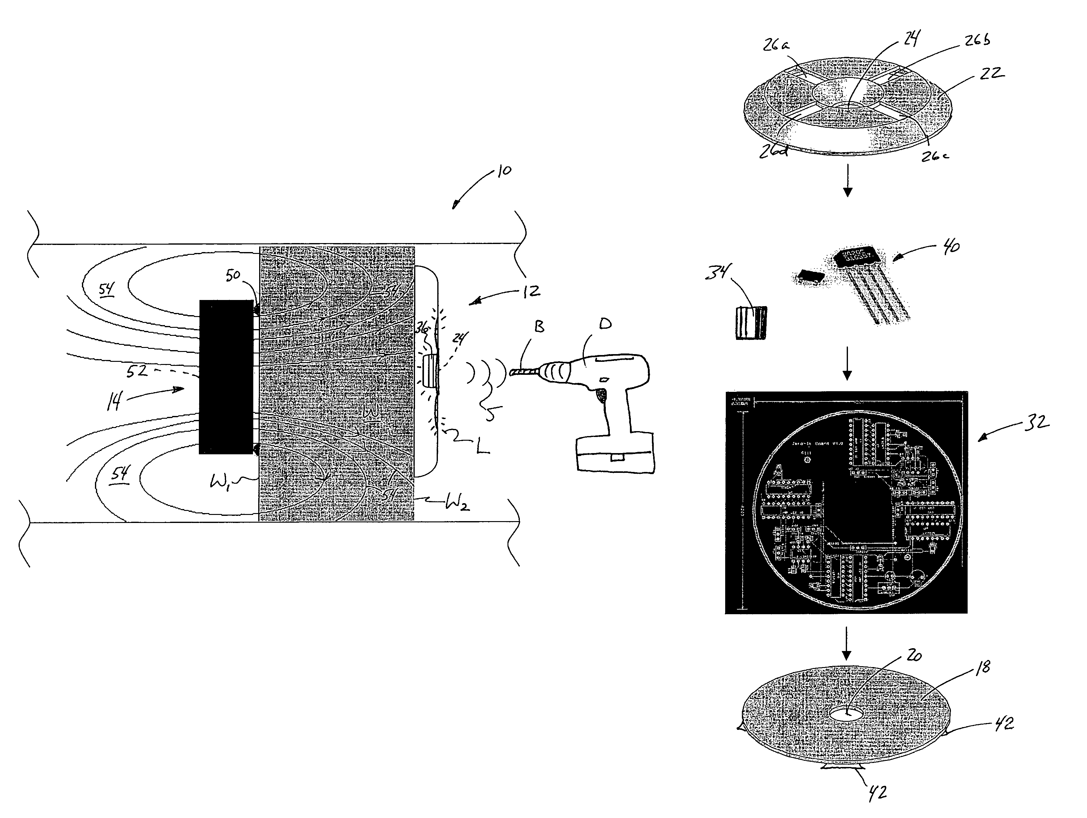
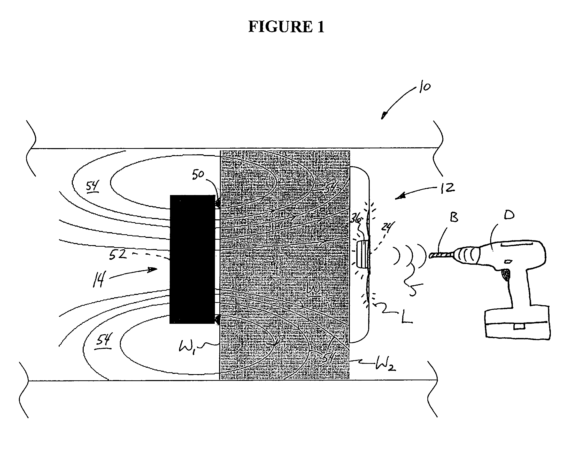
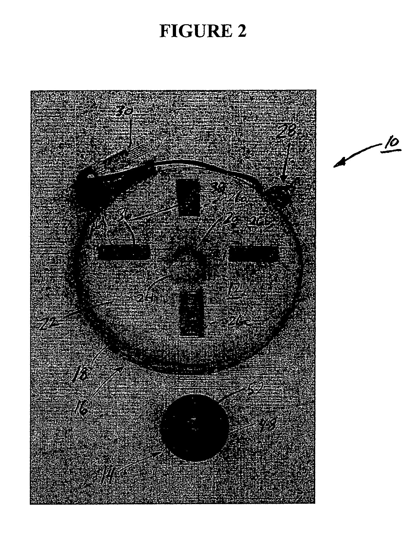
[0005]The present invention is directed in general to a system for precisely marking a reference point on a surface in order to cut through the reference point from a blind spot. The system generally includes a locator or sensor and a marker or transmitter. The transmitter is placed on a blind side of a surface, and the locator is used to locate or sense a signal emanating from the transmitter using one or more indicators on the locator. The indicators provide visual and audible targeting cues to mark the opposing side of the surface precisely opposite the transmitter. The component parts of the invention are simple and economical to manufacture, assemble and use, and other advantages of the invention will be apparent from the following description and the attached drawings, or can be learned through practice of the invention.
[0011]The indicator in this aspect of the invention can be or include an audio device. The audio device can emit a sound from about fifteen inches to about ten inches proximate the emitter. The audio device can emit a chirping tone from about fifteen inches to about ten inches proximate the emitter. The audio device when proximate about ten inches to about one inch from the emitter can increase a rate of the chirping tone or increase a loudness level of the chirping tone. The audio device can also emit a steady tone from about 0.25 inches to about one inch proximate the emitter.
[0020]The indicator is an audio device. The audio device is configured to emit a chirping tone from about fifteen inches to about ten inches proximate the magnetic emitter. The audio device proximate about ten inches to about one inch from the magnetic emitter increases a rate of the chirping tone. The audio device proximate about ten inches to about one inch from the magnetic emitter increases a loudness level of the chirping tone. The audio device is configured to emit a steady tone from about 0.25 inches to about one inch proximate the magnetic emitter.

Problems solved by technology

Unfortunately, most installation technicians do not have the time or tools to make precision measurements and their cable installations are often unsatisfactory.
Foremost, manual measurements are time consuming due to the large number of measurements that must be made and due to the difficulty in transferring those measurements to the opposite side of the structure.
This approach often leads to numerous unnecessary holes being drilled that of course must be patched or repaired to return the structure to its original condition.
Ironically, the unnecessary holes are often due to the multiple measurements, which are meant to provide precision but can be confusing and lead to mismarked reference points.
Moreover, this conventional measurement approach is costly due to the time associated with performing the initial measurements as well as the time and cost associated with patching or otherwise repairing the unnecessary holes.
However, these devices tend to be bulky and excessively complex, especially for a layman for use in a home project.
Moreover, for an occasional home project, the existing devices can be cost prohibitive.

Method used


Image

  • Blind spot targeting system
  • Blind spot targeting system
  • Blind spot targeting system

Examples


example

[0060]To construct a prototype of the blind spot targeting system 10, preliminary measurements indicated a need to amplify a sensor signal to power the LED bars 36 as well as to remove a 2.5-volt quiescent signal. Since original estimates placed desired gain at about 25, a single-stage differential amplifier was selected for all amplification, and designed around a rail-to-rail, low-power, single-supply op amp such as model TLV2452 available from Texas Instruments, 12500 TI Boulevard Dallas, Tex. The gain of about 25 was estimated assuming the Hall-effect sensors would have a swing between 2.5 and 2.55.

[0061]Since the TI chip has two amplifiers inside, each chip was tied to two sensor-display systems. To remove the 2.5-volt quiescent signal, a 2.5-volt source (from the power circuit) was placed onto one side of the differential amplifier such that the amplifier would amplify the remaining signal based on the ratio of the feedback resistors to the input resistors. See, e.g., FIG. 6 f...


PUM


Abstract

A blind spot targeting system for establishing a cutting point includes a locator with a housing having an indicator and a signal-sensing device. The housing has a hole therethrough, and the indicator is in electronic communication with the signal-sensing device for indicating a cutting point on a first side of a structure. A transmitter is also included, which has a complementary hole therethrough. The transmitter is for placement on a second side of the structure for emitting a signal, which the signal-sensing device senses. The indicator in communication with the signal-sensing device indicates alignment of the hole and the complementary hole to establish the cutting point for cutting through the hole into the first side of a structure and possibly through the second side of the structure in a direction of the complementary hole.

Description

CROSS-REFERENCE TO RELATED APPLICATIONS[0001]This application claims benefit of U.S. Provisional Patent Application Ser. No. 60 / 731,683 entitled “Blind Spot Targeting System”, filed Oct. 31, 2005.BACKGROUND OF THE INVENTION[0002]In residential or commercial construction, precisely determining a reference point on one side of a structure such as a wall, floor or ceiling from an opposite side of the structure is required to avoid unnecessary trial and error as well as damage to the structure. For example, when installing a ceiling fan, a workman must know exactly where to cut a hole on the one side of the ceiling in order to line up with an incoming conduit on the opposite side of the ceiling, in an attic for instance, without cutting into a truss or beam. Likewise, if the workman cuts from the attic side without a precise reference point, the hole for the ceiling fan may be off-center in the room below. By way of further example, a customer will request that a cable or satellite tele...

Claims


Application Information

Patent Timeline
IPC IPC(8): G01R19/00G01B7/14G01V3/08
CPCG01V3/081
Inventor GASQUE, JR., SAMUEL N.
Owner GASQUE JR SAMUEL N
Learn More