CPP with elongated pinned layer

a pinned layer and elongated technology, applied in the field of magnetic gmrtype read heads, can solve the problems of limited signal detection, shield-to-shield spacing, and increased pinned layer length, so as to reduce shield-to-shield spacing, increase the probability of spin interaction, and increase the effect of pinned layer length

Active Publication Date: 2008-06-03
HEADWAY TECH INC
View PDF21 Cites 31 Cited by
  • Summary
  • Abstract
  • Description
  • Claims
  • Application Information

AI Technical Summary

Benefits of technology

[0013]Another object of at least one embodiment of the present invention has been to Improve dR by increasing the length of spin interaction.
[0015]A further object of at least one embodiment of the present invention has been to reduce shield-to-shield spacing by eliminating a conductor layer in the gap.
[0016]These objects have been achieved by increasing the length of the AFM layer relative to that of both the free and spacer layers. The length of the pinned layer is also increased, but by a lesser amount, an abutting conductive layer being inserted to fill the remaining space over the AFM layer. The extended pinned layer increases the probability of spin interaction while the added conducting layer serves to divert sensor current away from the bottom magnetic shield which is now no longer needed for use as a lead.

Problems solved by technology

However, the signal amplitude of a CPP head is generally too small to be practically useful, because of low dR / R.
Since the thickness of a CPP device is relatively small, being limited by the shield-to-shield spacing, it cannot contribute much and therefore the signal that can be detected is limited.
Current CPP GMR configuration suffers from an additional problem.

Method used


Image

  • CPP with elongated pinned layer
  • CPP with elongated pinned layer
  • CPP with elongated pinned layer

Examples


Embodiment Construction

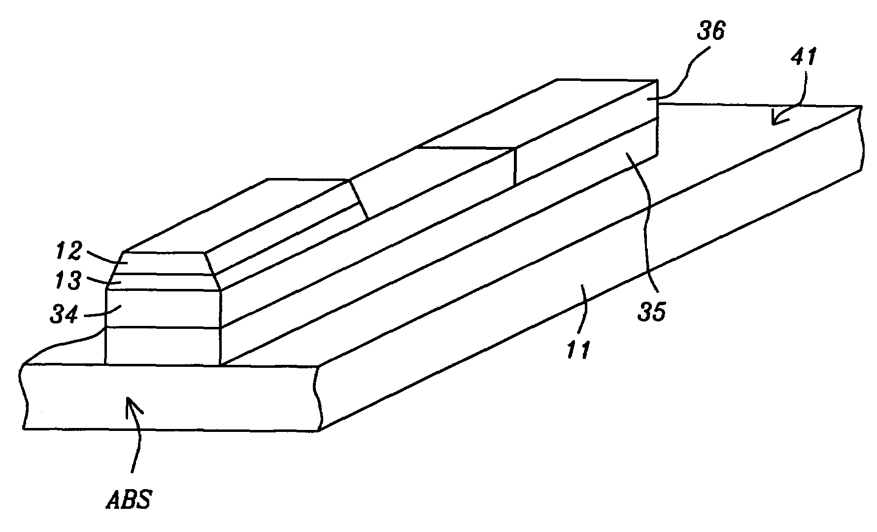
[0023]The invention includes two novel features:

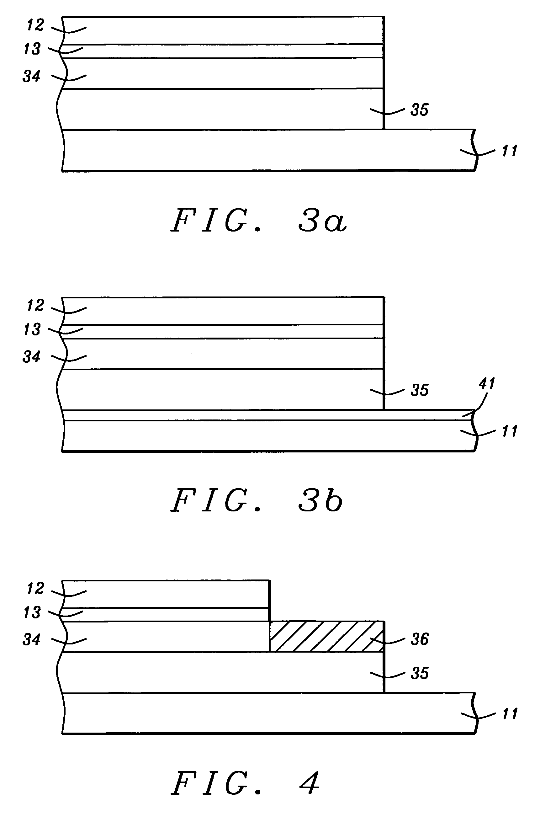
1. Elongating both the pinned and the pinning layers at the back side. The increased length is about 0.05 microns.

2. A conductor is added and abutted to the pinned and / or pinning layers.

[0024]The result of these features is that the bias current is forced to flow from the top conductor down through free layer and spacer and then to turn at the pinned layer, running out at the back side and entering the conducting lead. Thus only a portion of the bias current flows because of its high resistance.

[0025]Since the current flows in the elongated pinned layer, it has a longer interaction distance and therefore, dR is increased.

[0026]Since the current bypasses the high resistance (parasitic) portion of the head circuit, total R is reduced, thereby increasing dRIR.

[0027]In some prior art, a highly conductive layer is inserted between the magnetic shield and the AFM layer in order to direct current flow. However, this increases the total GMR he...


PUM

PropertyMeasurementUnit
lengthaaaaaaaaaa
lengthaaaaaaaaaa
lengthaaaaaaaaaa

Abstract

CPP magnetic read head designs have been improved by increasing the length of the AFM layer relative to that of both the free and spacer layers. The length of the pinned layer is also increased, but by a lesser amount, an abutting conductive layer being inserted to fill the remaining space over the AFM layer. The extended pinned layer increases the probability of spin interaction while the added conducting layer serves to divert sensor current away from the bottom magnetic shield which now is no longer needed for use as a lead.

Description

FIELD OF THE INVENTION[0001]The invention relates to the general field of magnetic GMR-type read heads with particular reference to GMR enhancement in a CPP device.BACKGROUND OF THE INVENTION[0002]The principle governing the operation of most magnetic read heads is the change of resistivity of certain materials in the presence of a magnetic field (magneto-resistance or MR). Magneto-resistance can be significantly increased by means of a structure known as a spin valve where the resistance increase (known as Giant Magneto-Resistance or GMR) derives from the fact that electrons in a magnetized solid are subject to significantly less scattering by the lattice when their own magnetization vectors (due to spin) are parallel (as opposed to anti-parallel) to the direction of magnetization of their environment.[0003]The main elements of a spin valve can be seen in FIG. 1. They are lower shield / conductor layer 11 on which is (magnetically) free layer 12. Directly above the free layer is non-...

Claims


Application Information

Patent Timeline
Patent Type & Authority Patents(United States)
IPC IPC(8): G11B5/33G11B5/127
CPCG11B5/127G11B5/187
Inventor LIN, CHARLES C.LI, MIN
Owner HEADWAY TECH INC
Why Eureka
Try Eureka