Heat dissipation device

a heat sink and heat dissipation technology, applied in the direction of fluid heaters, air heaters, light and heating apparatus, etc., can solve the problems of reducing the heat dissipation efficiency of the heat sink system, cpu overheating and damage, and airflow generated by the fan being prone to escap

Inactive Publication Date: 2008-06-03
HON HAI PRECISION IND CO LTD +1
View PDF10 Cites 4 Cited by
  • Summary
  • Abstract
  • Description
  • Claims
  • Application Information

AI Technical Summary

Benefits of technology

[0005]According to a preferred embodiment of the present invention, a heat dissipation device for an electronic unit comprises a heat sink, a pair of fan holders and a fan mounted on the heat sink via the fan holders. The heat sink includes a base with a plurality of fins extending upwardly therefrom along a lateral direction thereof. The base forms a pair of lateral walls at two opposite lateral sides thereof. The fins are sandwiched between the lateral walls. A pair of supporting plates extend from the lateral walls for securing the fan holders on the heat sink. The fan holders are secured between bottom surfaces of the supporting plates and tops of higher ones of the fins. The fan holders cooperate with the lateral walls of the heat sink to encompass a top of the fins to prevent airflow generated by the fan from escaping from the top of the fins.

Problems solved by technology

Without proper cooling, the heat generated by the CPU can quickly cause the CPU to overheat and damage the CPU.
However airflow generated by the fan is prone to escape from gap between the top of the fins and a bottom of the fan.
There is a high flow resistance in a central portion of the heat sink, and cold air therefore can not enter the central portion of the heat sink, thereby reducing heat dissipation efficiency of the heat sink system.
Therefore, the heat generated by the CPU can not be transmitted to the fins effectively and quickly.

Method used


Image

  • Heat dissipation device
  • Heat dissipation device
  • Heat dissipation device

Examples


Embodiment Construction

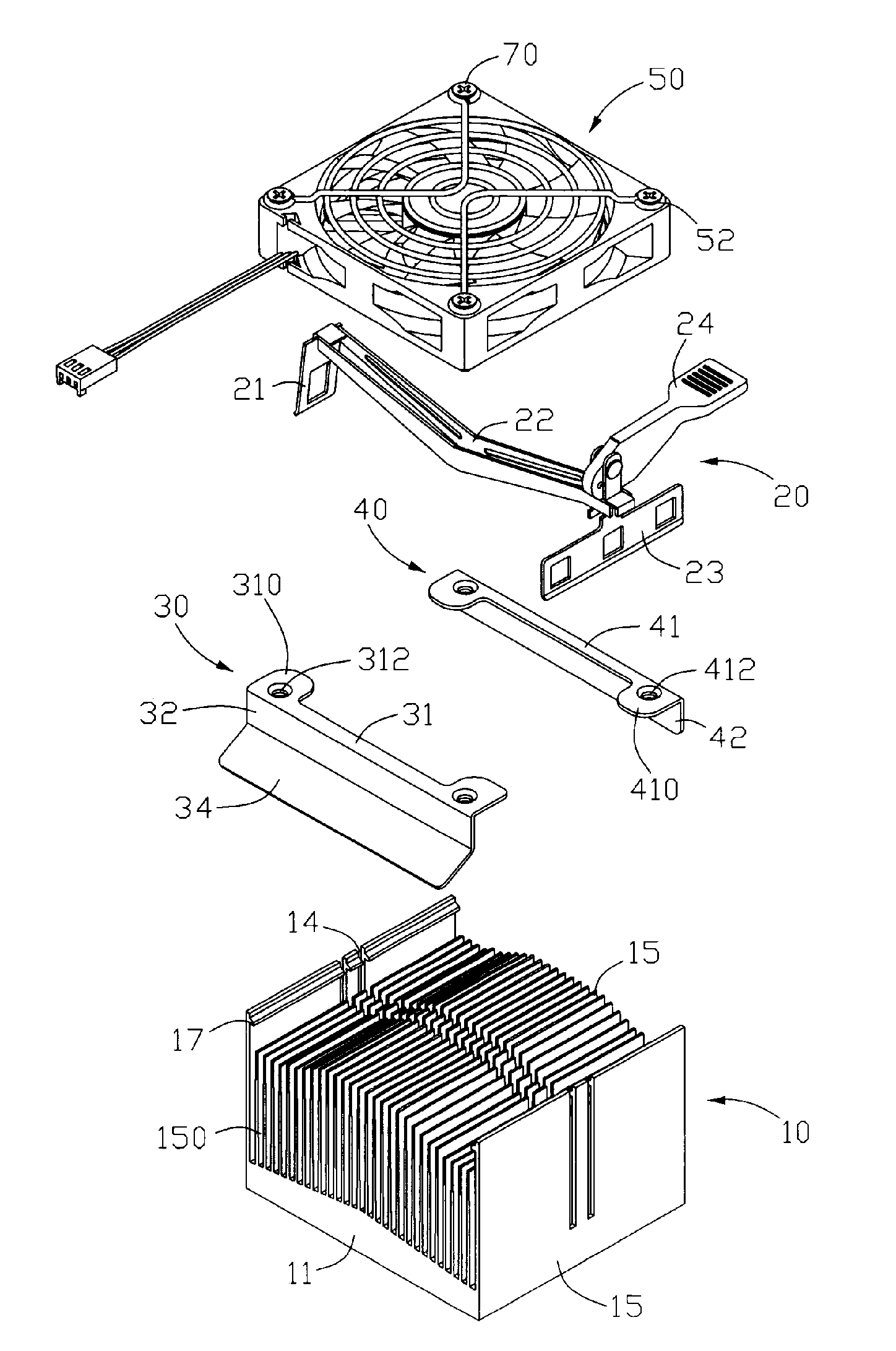
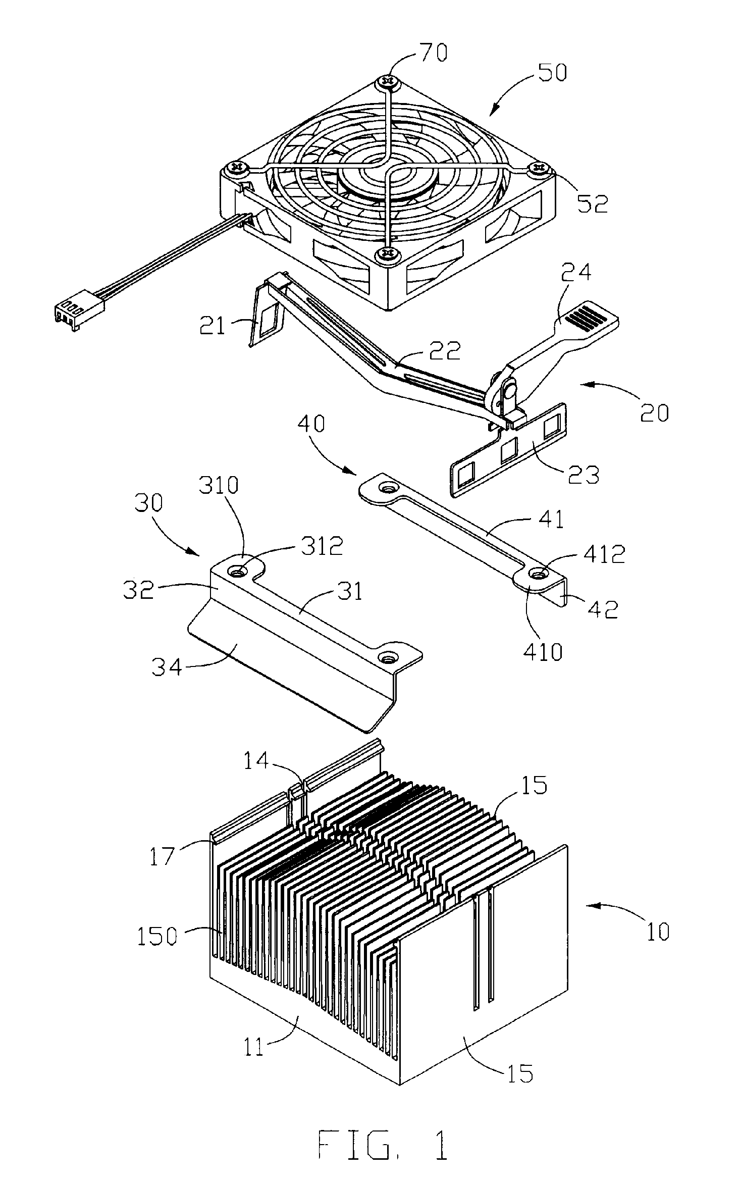
[0011]Referring to FIG. 1, a heat dissipation device in accordance with a preferred embodiment of the present invention comprises a heat sink 10, a fan 50, a first and second discrete fan holders 30, 40 mounting the fan 50 onto the heat sink 10 and a clip 20 for securing the heat sink 10 on a main heat-generating electronic component such as a CPU (not shown) located on a printed circuit board (not shown).

[0012]The heat sink 10 comprises a base 11 having a bottom face for contacting with the CPU and a top face on an opposite side to the bottom face, and a plurality of spaced and parallel fins 15 integrally extending upwardly from the top face of the base 11 along a lateral direction of the base 11. The base 11 has an arc-shaped cross section, i.e., a middle portion of the base 11 being thicker than two lateral sides of the base 11. A plurality of channels 150 are defined between the fins 15. The fins 15 on the middle of the base 11 are higher than that on the lateral sides of the ba...


PUM


Abstract

A heat dissipation device for an electronic unit includes a heat sink (10), a pair of fan holders (30, 40) and a fan (50) mounted on the heat sink via the fan holders. The heat sink includes a base (11) with a plurality of fins (15) extending upwardly therefrom along a lateral direction thereof. The base forms a pair of lateral walls at two opposite lateral sides thereof. The fins are sandwiched between the lateral walls. A pair of supporting plates (17) extend from the lateral walls for mounting the fan holders on the heat sink. The fan holders cooperate with the lateral walls of the heat sink to encompass a top of the fins to prevent airflow generated by the fan from escaping from the top of the fins.

Description

FIELD OF THE INVENTION[0001]The present invention relates to a heat dissipation device, and particularly to a heat dissipation device having a pair of fan holders for achieving greater heat dissipation efficiency.DESCRIPTION OF RELATED ART[0002]As computer technology continues to advance, electronic components such as central processing units (CPUs) of computers are made to provide faster operational speeds and greater functional capabilities. When a CPU operates at a high speed in a computer, its temperature undergoes rapid increase. Cooling is especially important for the CPU of the computer. Without proper cooling, the heat generated by the CPU can quickly cause the CPU to overheat and damage the CPU. It is therefore desirable to dissipate the heat quickly, for example by using a heat sink system assembled within the computer, so that the CPU of the computer operates within a normal temperature range.[0003]A related heat sink system mounted on CPUs generally includes a heat sink,...

Claims


Application Information

Patent Timeline
Patent Type & Authority Patents(United States)
IPC IPC(8): H05K7/20
CPCH01L23/4093H01L23/467H01L2924/0002H01L2924/00
Inventor LONG, JUNLI, HAOLI, TAO
Owner HON HAI PRECISION IND CO LTD
Why Eureka
Try Eureka