Device and method for pressure indication

a pressure indication and device technology, applied in the direction of dilators, respiratory masks, trachea tubes, etc., can solve the problems of bringing certain possible dangers to light, excessive cuff inflation, and the potential damage of nerves and tissues around the hypopharynx, etc., to achieve easy connection or integral formation, easy to obtain an objective measure of cuff pressure, and simple and easily referenced indication

Inactive Publication Date: 2008-06-10
TELEFLEX LIFE SCI PTE LTD
View PDF19 Cites 60 Cited by
  • Summary
  • Abstract
  • Description
  • Claims
  • Application Information

AI Technical Summary

Benefits of technology

[0014]Preferably, the distal end of the device is adapted to connect to a syringe. In one embodiment, the distal end includes a spring loaded valve and a female luer and is arranged so that the valve is actuated upon insertion of the syringe into the female luer, thereby opening the valve and allowing fluid communication from or into the syringe into or from the device. In an alternative embodiment, a stopper valve is used instead of the spring loaded valve. The stopper valve operates to provide a similar effect.
[0031]Advantageously, the pressure indication device of the invention is small and easily connected to, or integrally formed on the end of, the cuff inflation tube of the airway device so as to provide a simple and easily referenced indication of the internal cuff pressure. This means that medical personnel can easily obtain an objective measure of the cuff pressure without having to connect a manometer to the cuff inflation tube. The pressure indication device and methods of use therefor may advantageously reduce the incidence of damage to the hypopharynx area of a patient due to over-inflation of the cuff of the laryngeal mask or damage otherwise resulting from inadequate inflation or over-inflation of an inflatable medical cuff.

Problems solved by technology

The greater prevalence in use of the laryngeal mask has brought certain possible dangers to light.
Due to human errors and the possible diffusion of nitrous oxide into the silicone cuff, the cuff may be excessively inflated.
Such excessive inflation of the cuff has the potential to damage nerves and tissues around the hypopharynx, and this potential danger has been the subject of scientific papers in anaesthesia journals.
Manometers are, however, relatively expensive and somewhat bulky and can be inconvenient to connect to the cuff inflation valve as the valve is usually close to the patient's mouth.
Similar problems can occur in other airway devices having an inflatable cuff, such as endotracheal tubes, for example.

Method used


Image

  • Device and method for pressure indication
  • Device and method for pressure indication
  • Device and method for pressure indication

Examples


Embodiment Construction

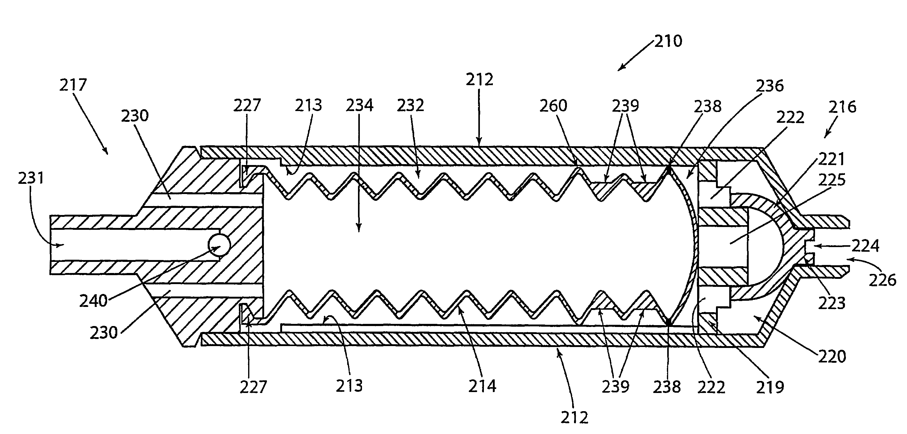
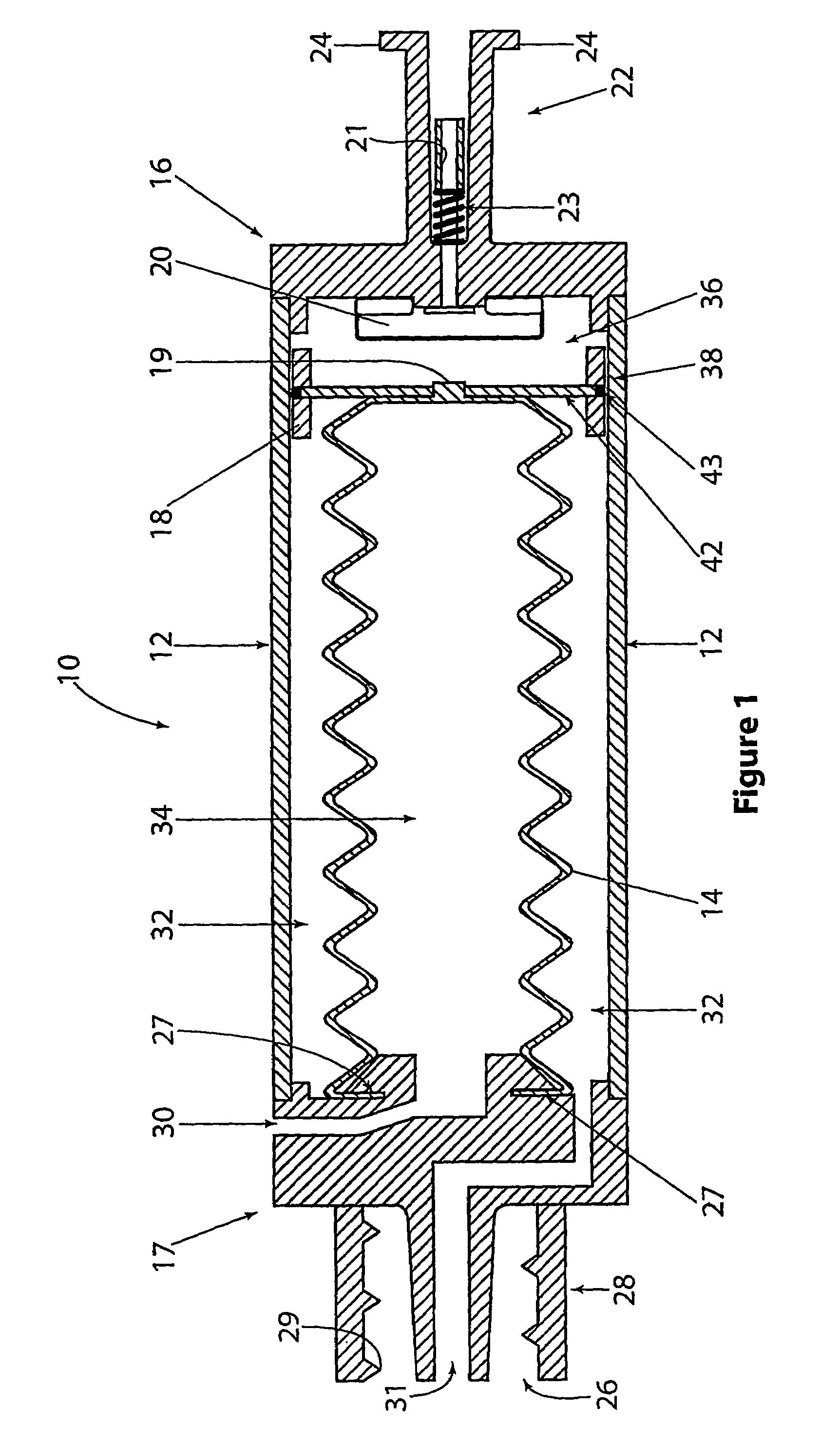
[0053]Embodiments of the invention are described hereinafter generally in relation to their applicability to laryngeal masks. It should be understood, however, that the invention is also applicable to other applications requiring pressure, indications of a similar magnitude and to other airway devices having air-inflatable cuffs, such as some endotrachial tubes.

[0054]Referring to FIG. 1, one embodiment of the invention relates to a pressure indicator device 10 having a cylindrical outer wall 12, a bellows 14 and female and male ends 16, 17 (also referred to as the distal and proximal ends, respectively). The bellows 14 is located inside the outer wall 12 and moves concentrically therewithin in response to differential pressure. One end of the bellows 14 is attached to the male end 17, while the other end of the bellows, in its relaxed state, extends towards the female end 16. At the male end 17, the bellows is open to atmospheric pressure via a vent passage 30, while the other end o...


PUM

PropertyMeasurementUnit
thicknessaaaaaaaaaa
thicknessaaaaaaaaaa
opening angleaaaaaaaaaa

Abstract

A device for indicating an internal pressure of an inflatable medical cuff, comprising: a membrane movable in response to a difference between the internal pressure and an external pressure; and movable indication means operably associated with the membrane for indicating, in use of the device, the internal pressure.

Description

FIELD OF THE INVENTION[0001]The present invention relates to a method and device for pressure indication. In particular, the invention relates to a method and device for indicating an air pressure of a cuff of a laryngeal mask or other airway device.BACKGROUND OF THE INVENTION[0002]In 1988, Dr. Archie Brain invented a new airway device, called the laryngeal mask, for delivering anaesthetic gases and oxygen to an unconscious patient during an operation. Prior to this, patients were commonly anaesthetised using an Endotrachael Tube running through the vocal cords of the patient into the trachea. Alternatively, a face mask connected to a gas source was held over the patient's nose and mouth.[0003]In use, the laryngeal mask is inserted into the pharangeal space (throat) deflated, and when correct positioning is observed, an inflatable cuff around the outside of the mask is inflated with air using a syringe. The syringe is inserted into an end of a valve which is connected to the cuff by...

Claims


Application Information

Patent Timeline
Patent Type & Authority Patents(United States)
IPC IPC(8): G01L13/02A61M16/04A61M16/06A61M29/00A62B9/02G01L7/06
CPCA61M16/044A61M16/0409A61M2016/0027G01L7/063
Inventor ESNOUF, PHILIP STUART
Owner TELEFLEX LIFE SCI PTE LTD
Why Eureka
Try Eureka