Water feature with an LED system

a technology of led lighting and water features, applied in the direction of fixed installation, lighting and heating apparatus, lighting applications, etc., can solve the problems of affecting the view of the feature and the overall aesthetic, the visual effect of the light that is reflected to the eye is minimal, and the available light is not used efficiently, so as to achieve a higher luminosity light

Inactive Publication Date: 2008-06-10
DOYLE KEVIN
View PDF31 Cites 37 Cited by
  • Summary
  • Abstract
  • Description
  • Claims
  • Application Information

AI Technical Summary

Benefits of technology

[0012]An object of the invention is to provide higher intensity Light Emitting Diodes without diminishing their operational life through the additional cooling provided by direct contact with the water in the water feature.
[0013]An object of the instant invention is to provide illumination of water features by using light emitting diodes which are placed inside the water feature or inserted from the outside of the water feature with the tips of the LEDs exposed directly to the water, using the water as a means of cooling the LEDs and preventing them from overheating and shortening the life of the LEDs.

Problems solved by technology

While such illumination effects can be quite cost effective, the available light is not used efficiently and the visual effect that results from the light that is reflected to the eye is minimal.
This of course would impair the view of the feature and the overall aesthetic.
These transmission box arrangements are clumsy and bulky and there is considerable light loss due to transmission losses.
These losses occur as the light enters the water tight chamber and on through the lens to the outlet due to dispersion, reflection, and refraction.
However, these devices simply extended the watertight chamber concept further into the path of the water.
While this increases luminosity due to the increased surface area of the enclosure, significant transmission losses still occur due to the space in the watertight enclosure placed around the high intensity lamp.
In addition, the location of the lighting system inside the water feature makes the necessary and frequent replacement of bulbs in such systems difficult and costly to manage.
However, these fiber optically lit features suffer significantly from the lower luminescence of the transmitted light from the light pump to the tips of the fiber optics, as there are transmission losses and the tips act only as point light sources.
In addition to the luminosity problems, the fiber optic lighting systems are costly and significantly more difficult to install and maintain than conventional lights.
The fiber optic fibers are very delicate, susceptible to damage even from a slight impact, which makes proper installation difficult.
To compound this problem, repair of the individual fibers is extremely difficult and costly.
Similar problems exist with maintenance of such features.

Method used


Image

  • Water feature with an LED system
  • Water feature with an LED system
  • Water feature with an LED system

Examples


Embodiment Construction

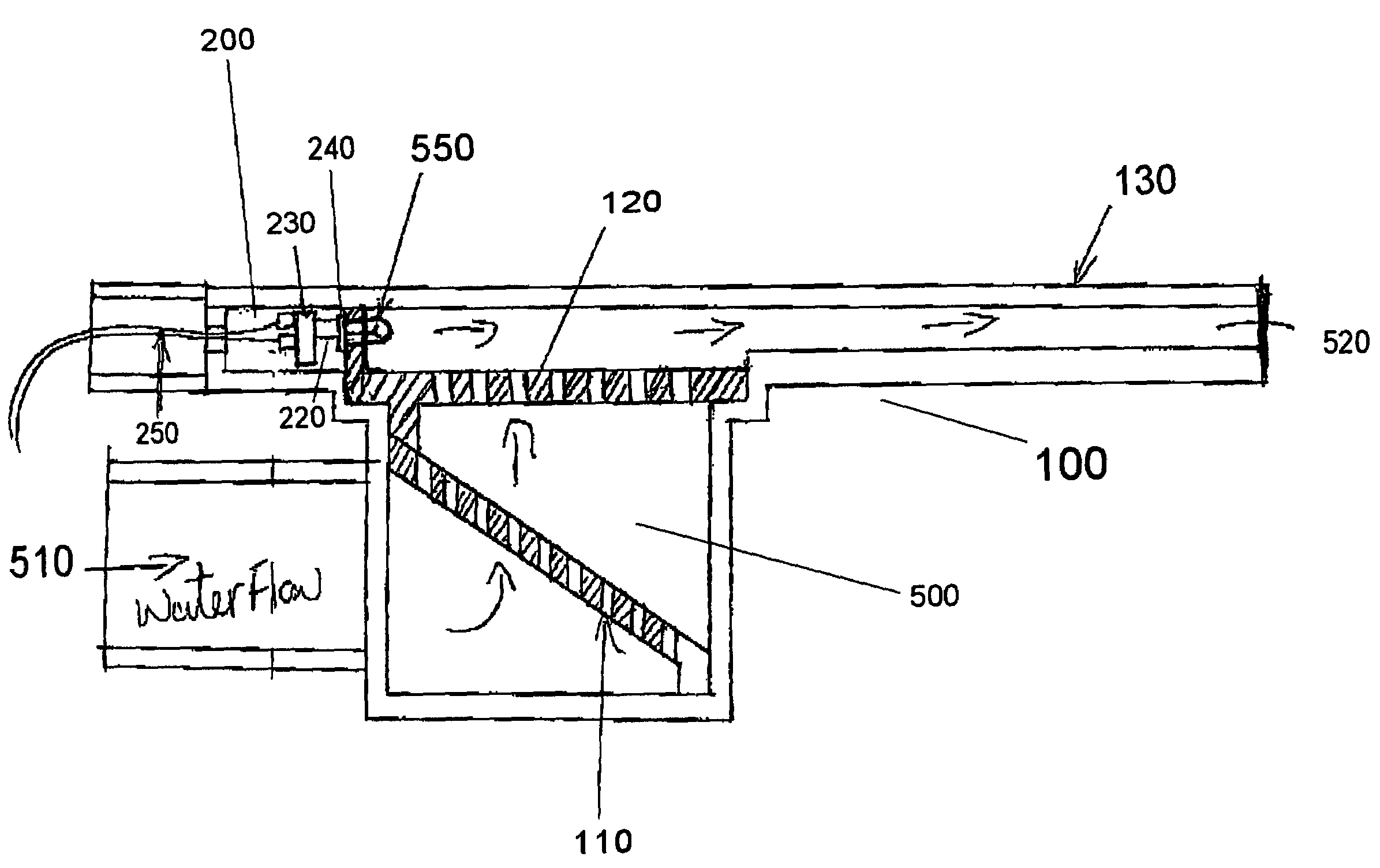
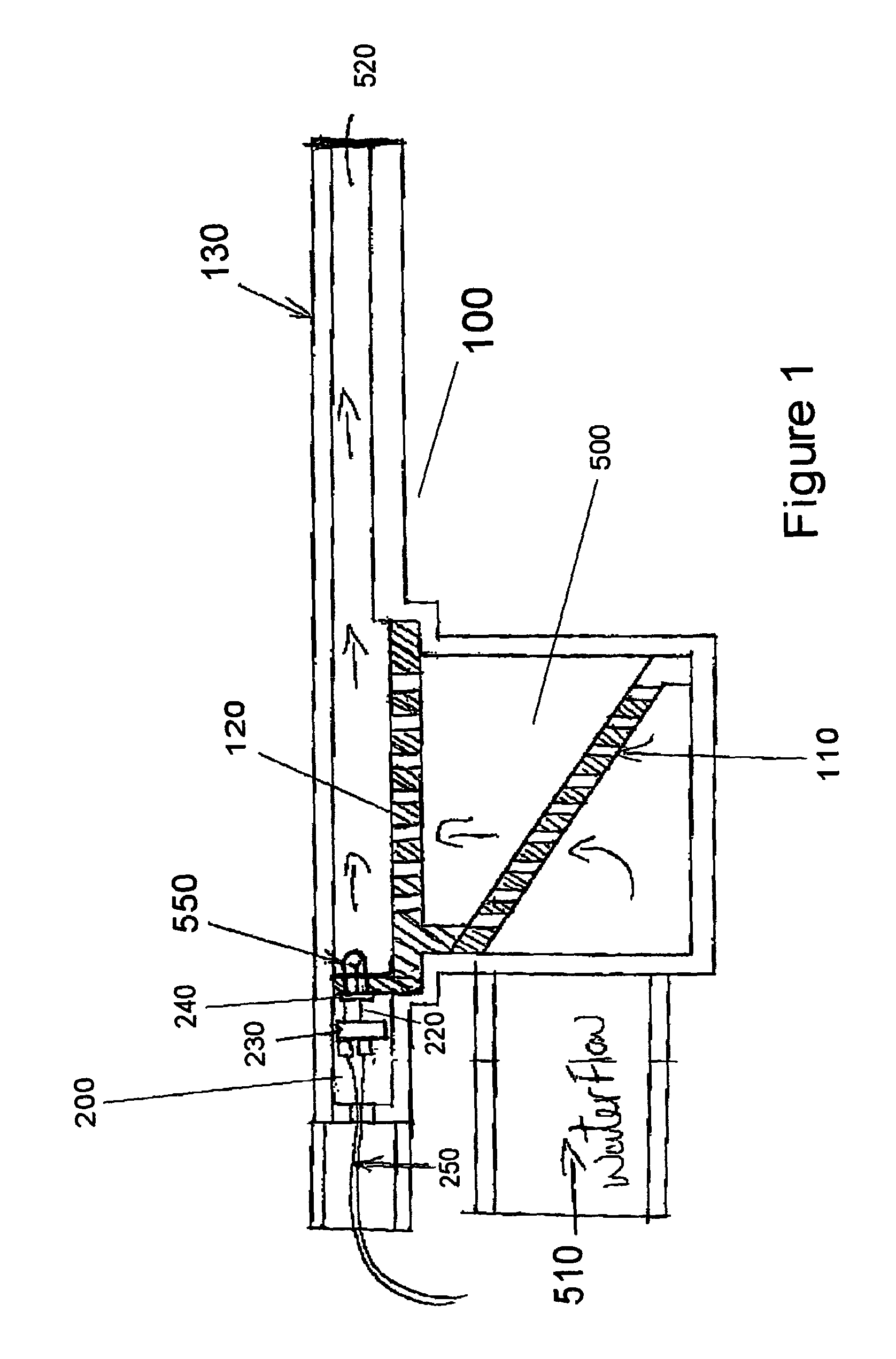
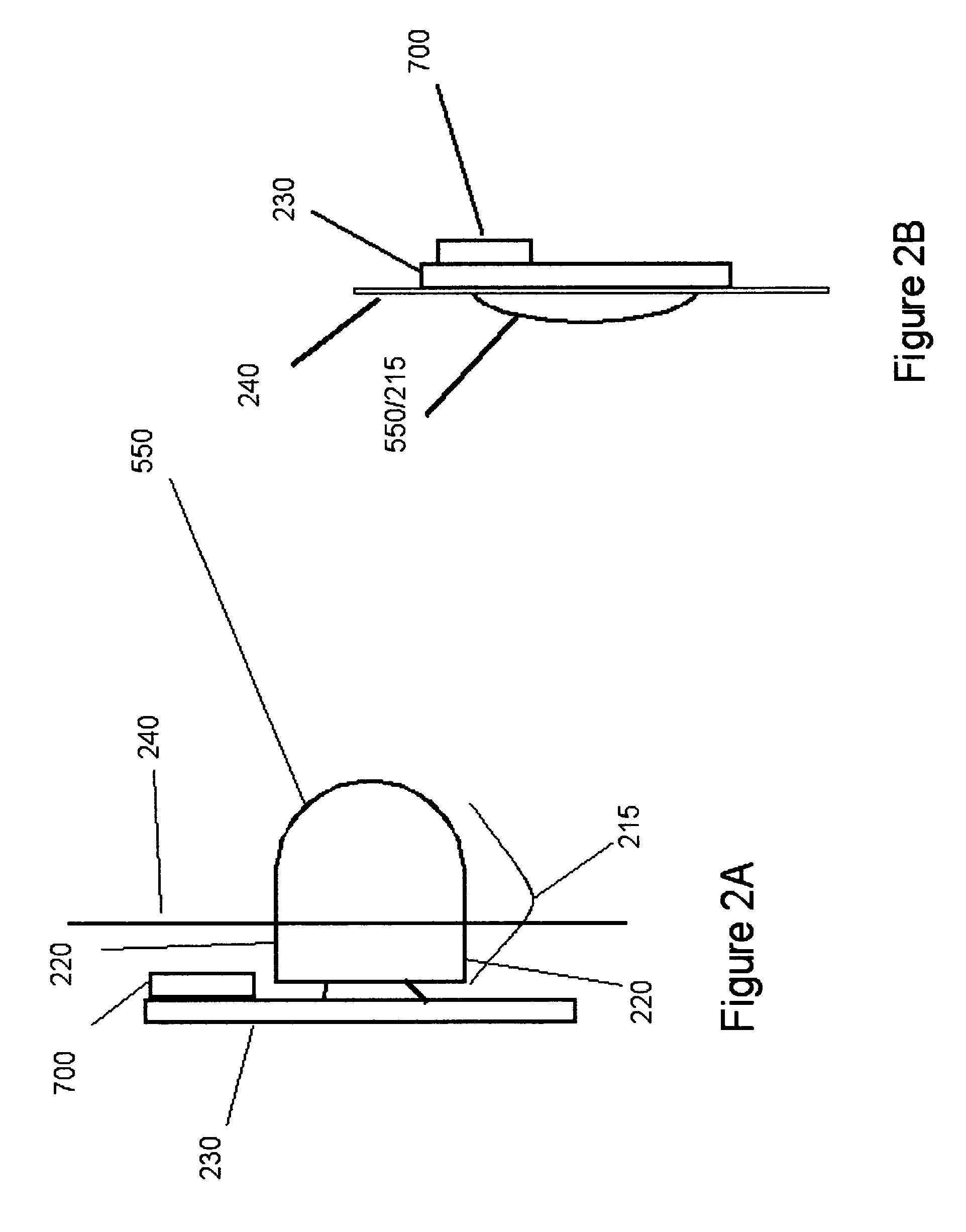
[0032]The instant invention is directed to a water feature having an LED system with at least a portion of the LED in direct contact with the water. In the exemplary embodiments, at least one LED is at least partially in direct contact with the water, for instance as it flows through a jet, nozzle, bubbler, water sheet, rests in a pool or is similarly held in a water feature. The LED system can be run at higher intensities, since the water in the water feature acts as a very large heat sink to remove the additional heat from higher intensity. This direct contact also improves luminosity and allows for a wide variety of color changes not possible in heretofore known lighting systems. These color changes can be changed in such a way that provides a very specific and hereto for unachievable color washing effect, such that the water feature, for instance a waterfall, laminar water tube, jet, bubbler, water sheet, fountain, pool, or similar feature, can be different colors at the same ti...


PUM


Abstract

A water feature having a housing with an electronics section and a water channel. A printed circuit board with an at least one light emitting diode (LED) where at least a portion of the at least one LED is in direct contact with the water while the electrical section remains waterproof.

Description

BACKGROUND OF THE INVENTION[0001]1. Field of the Invention[0002]The invention generally relates to an apparatus and method for lighting water in a water feature, particularly for lighting water with Light Emitting Diodes (LEDs) at least partially in direct contact with the water.[0003]2. Background of the Invention[0004]Increasingly, the popularity of using water as an integral part of domestic landscaping has moved landscapers to include greater numbers of decorative water features. These features are incorporated in swimming pools, spas, ponds, lakes, and other water features and sources in the typical yard. In addition to domestic landscaping, commercial landowners have also been following the trend toward more decorative water elements through fountains, pools, ponds, lakes and such. In response, companies have developed a myriad of features that span the range of naturally occurring water features, such as faux waterfalls complete with jutting rock outcroppings, to more artisti...

Claims


Application Information

Patent Timeline
Patent Type & Authority Patents(United States)
IPC IPC(8): F21V33/00
CPCB05B15/00B05B17/08F21S8/00F21S10/002F21S10/02F21V23/0407F21V33/004H05K3/284F21V29/30F21W2121/02F21W2131/401F21Y2101/02H05K2201/10106H05K2203/1311F21Y2115/10F21V29/56
Inventor DOYLE, KEVIN
Owner DOYLE KEVIN
Why Eureka
Try Eureka