Carriage assembly of a hard disk drive

a hard disk drive and carriage assembly technology, applied in the direction of integrated arm assemblies, laminating printed circuit boards, instruments, etc., can solve the problems of fluctuation in the electrical bonding strength between the flying and the transmission of ultrasonic vibration, and the replacement of the flying becomes impossibl

Inactive Publication Date: 2008-06-10
TOSHIBA STORAGE DEVICE CORP
View PDF8 Cites 38 Cited by
  • Summary
  • Abstract
  • Description
  • Claims
  • Application Information

AI Technical Summary

Benefits of technology

[0030]With this construction, by applying heat during the ultrasonic bonding of the flying lead and the bonding terminal, the fluidity of the adhesive is increased, or deformation of the adhesive layer is facilitated, so that it becomes possible to make the thickness of the adhesive layer more uniform.
[0048]According to the present invention, it is possible to uniformly and reliably bond the flying leads of a long tail suspension circuit board and the bonding terminals of a flexible printed circuit board, so that the problem of the flying leads breaking when the flying leads are pulled off the bonding terminals does not occur.

Problems solved by technology

This means that the pressing force of the ultrasonic tool T does not act uniformly on the plurality (in this example, four) flying leads 15a and the bonding terminals 16a, and therefore the transmission of the ultrasonic vibration is also not uniform, resulting in the problem of fluctuations occurring in the electrical bonding strength between the flying leads 15a and the bonding terminals 16a.
This means that there are cases where the application of a large force to the flying leads 15a causes the flying leads 15a to break, resulting in the problem that replacement becomes no longer possible or the replacement process becomes difficult.

Method used


Image

  • Carriage assembly of a hard disk drive
  • Carriage assembly of a hard disk drive
  • Carriage assembly of a hard disk drive

Examples


first embodiment

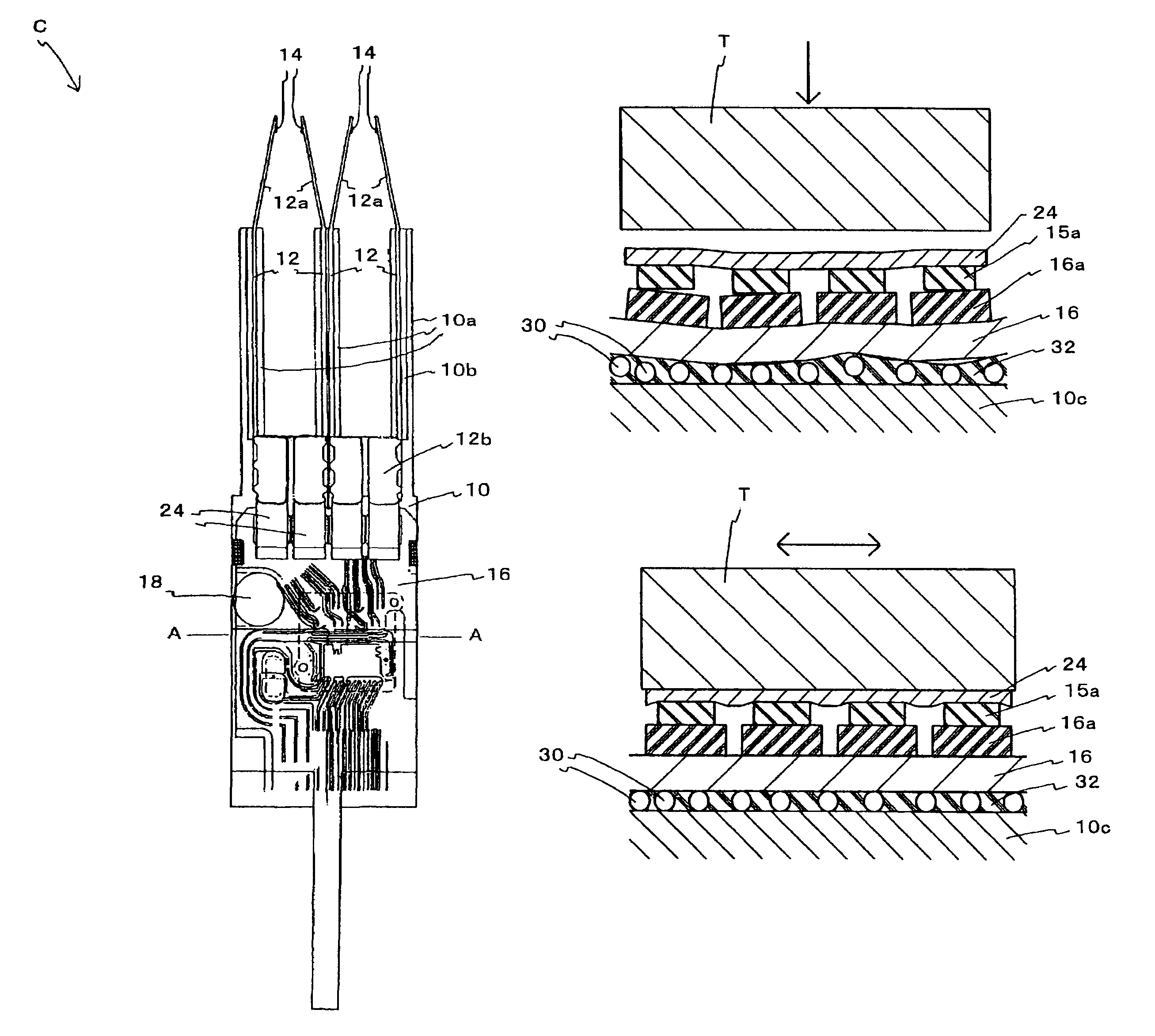
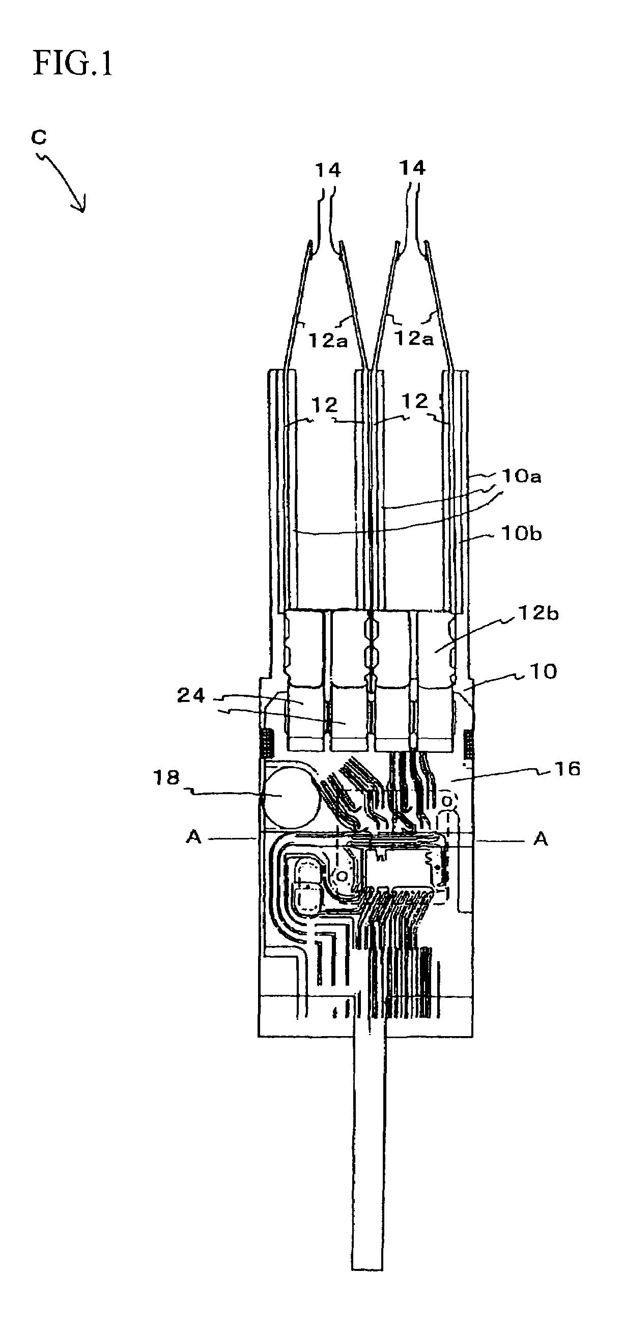
[0064]FIG. 1 is a side elevation of a carriage assembly C according to a first embodiment of the present invention.

[0065]It should be noted that parts of the construction that are the same as in the conventional carriage assembly Cx have been assigned the same reference numerals and description of such has been omitted.

[0066]In the carriage assembly C of this first embodiment, an insulating film 24 that is elastic is provided on an opposite side of the flying leads 15a to a surface that is bonded to the bonding terminals 16a.

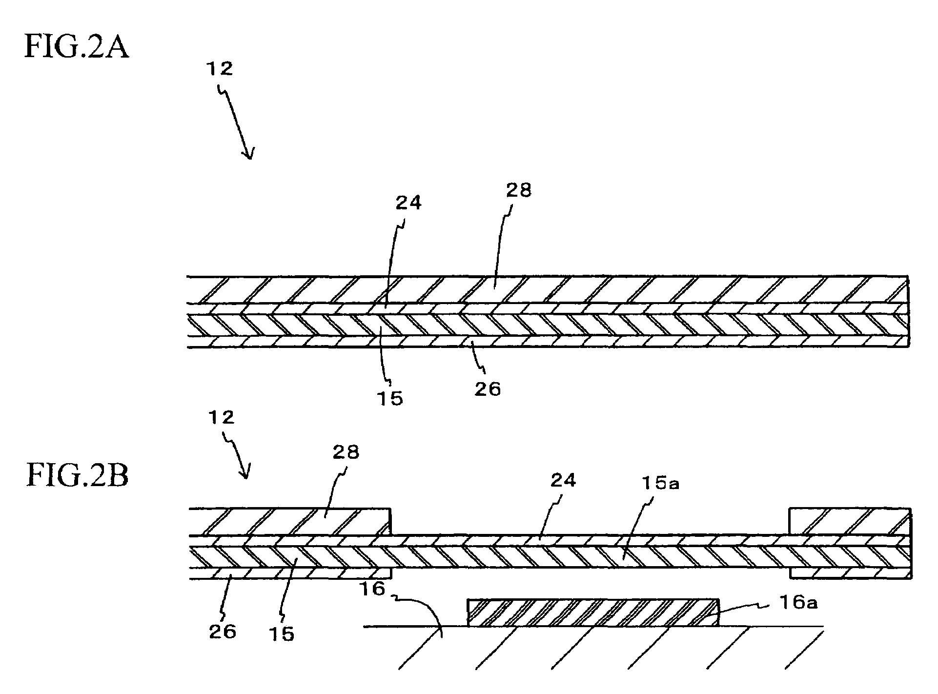
[0067]The method of forming the insulating film 24 will now be described with reference to FIGS. 2A and 2B.

[0068]FIG. 2A is a partial cross-sectional view in the lengthwise direction at a carriage main body 10 end of a long tail suspension circuit board 12 before the flying leads 15a are formed. The long tail suspension circuit board 12 includes a stainless steel plate 28, the wiring circuit 15, the insulating film 24 that insulates the stainless steel plate 28...

second embodiment

[0081]Next, a second embodiment of the present invention will be described.

[0082]It should be noted that parts of the construction that are the same as in the carriage assembly C of the first embodiment or the conventional carriage assembly Cx have been assigned the same reference numerals, description of such has been omitted, and only the differences will be described below.

[0083]As shown in FIG. 4, in the second embodiment, openings 24a are formed in the insulating film 24 of the first embodiment, which is provided on an opposite surface of the flying leads 15a to the surface bonded to the bonding terminals 16a, at positions corresponding to the parts bonded to the bonding terminals 16a. The openings 24a are formed so as to respectively correspond to the individual flying leads 15a and the bonding terminals 16a.

[0084]In this second embodiment, as shown in FIG. 5A (which is similar to FIG. 2B of the first embodiment) the flying leads 15a are formed by removing the stainless steel...


PUM

PropertyMeasurementUnit
flexibleaaaaaaaaaa
particle sizeaaaaaaaaaa
conductiveaaaaaaaaaa

Abstract

A carriage assembly of a hard disk drive is constructed so that the bonding of flying leads of a long tail suspension circuit board and bonding terminals of a flexible printed circuit board can be carried out uniformly and reliably, and the problem of the flying leads breaking when the flying leads are pulled off the bonding terminals does not occur. The flexible printed circuit board is attached to a reinforced part by an adhesive in which spacers with a substantially equal particle diameter are mixed, and the flying leads and the bonding terminals are bonded together by ultrasonic bonding by applying ultrasonic vibration in a state where the flying leads are pressed onto the bonding terminals. In addition, an insulating film is provided on an opposite surface of the flying leads to the surface bonded to the bonding terminals, and during the ultrasonic bonding, ultrasonic vibration is applied in a state where the flying leads are pressed via the insulating film onto the bonding terminals.

Description

BACKGROUND OF THE INVENTION[0001]1. Field of the Invention[0002]The present invention relates to a carriage assembly of a hard disk drive which is provided with a wiring circuit electrically connected to a magnetic head and includes a long tail suspension circuit board where part of the wiring circuit is formed as flying leads and a flexible printed circuit board on which bonding terminals to which the flying leads are bonded are provided.[0003]2. Related Art[0004]In recent years, in the field of hard disk drives (magnetic disk apparatuses), as the recording density of magnetic disks has increased and access speeds have become faster, the construction of a carriage assembly, and in particular the constructions of the suspension and flexible printed circuit board have been rationalized.[0005]More specifically, “suspension circuit boards”, where a wiring circuit is formed in advance on the surface or another part of the suspension that supports a magnetic head, are becoming more commo...

Claims


Application Information

Patent Timeline
Patent Type & Authority Patents(United States)
IPC IPC(8): G11B5/55G11B21/21G11B5/48
CPCG11B5/4833G11B5/4846G11B5/486G11B5/484H05K3/361H05K1/056H05K3/0058H05K3/328H05K3/386H05K2201/0969H05K2201/2009H05K2201/2036H05K2203/0285
Inventor KUBOTA, TAKASHIKOBAE, KENJI
Owner TOSHIBA STORAGE DEVICE CORP
Why Eureka
Try Eureka