Method and system for detecting ignition failure in a gas turbine engine

a gas turbine engine and ignition failure technology, applied in the ignition of the turbine/propulsion engine, engine starter, machines/engines, etc., can solve the problems of excessive energy consumption, failure of the turbine engine to start properly, and inadvertent extinguishing of the flame in the gas turbine engin

Active Publication Date: 2008-06-17
GENERAL ELECTRIC CO
View PDF28 Cites 42 Cited by
  • Summary
  • Abstract
  • Description
  • Claims
  • Application Information

AI Technical Summary

Benefits of technology

[0005]In another aspect, a gas turbine system is provided. The system includes a gas turbine engine that includes a combustor section and a turbine section, a drain line coupled to a low-point of at least one of the combustor section and the turbine section, a control system configured to receive a signal indicative of a failure of ignition of the combustor section, and prevent ignition of the combustor section until fuel introduced to the gas turbine engine is substantially removed from the gas turbine engine.
[0006]In yet another aspect, a computer program embodied on a computer readable medium for controlling a gas turbine engine system wherein the system includes a gas turbine engine that includes at least one combustor can. The computer program includes a code segment that receives user selection input data and then instructs the system to filter a gas turbine engine signal indicative of combustion in at least one of the combustor cans to only pass a portion of the signal that is. between at least one of approximately ten Hz to approximately twenty five Hz, approximately eighty Hz to approximately one hundred and twenty Hz, and approximately one hundred thirty Hz to approximately one hundred sixty Hz, compare the filtered signal to a predetermined lean blowout threshold, and control the gas turbine engine system to facilitate reducing a probability of a lean blowout event using the comparison.

Problems solved by technology

Sometimes the gas turbine engine fails to start properly, and / or the flame in the gas turbine engine may be inadvertently extinguished.
However, unburned accumulated fuel within the engine may pose a hazard during subsequent starting of the gas turbine engine, because, the left-over unburned fuel may ignite with the fuel supplied to the combustor during engine starting, thus providing an excessive amount of energy to the combustor and other parts of the gas turbine engine that may result in damage to such components.

Method used


Image

  • Method and system for detecting ignition failure in a gas turbine engine
  • Method and system for detecting ignition failure in a gas turbine engine
  • Method and system for detecting ignition failure in a gas turbine engine

Examples


Embodiment Construction

[0010]While the methods and systems are herein described in the context of a gas turbine engine used in an industrial environment, it is contemplated that the methods and systems described herein may find utility in other combustion turbine systems applications including, but not limited to, turbines installed in aircraft, watercraft, and land vehicles. In addition, the principles and teachings set forth herein are applicable to gas turbine engines using a variety of combustible fuels such as, but not limited to, gasoline, kerosene, diesel fuel, and jet fuel. The description hereinbelow is therefore set forth only by way of illustration, rather than limitation.

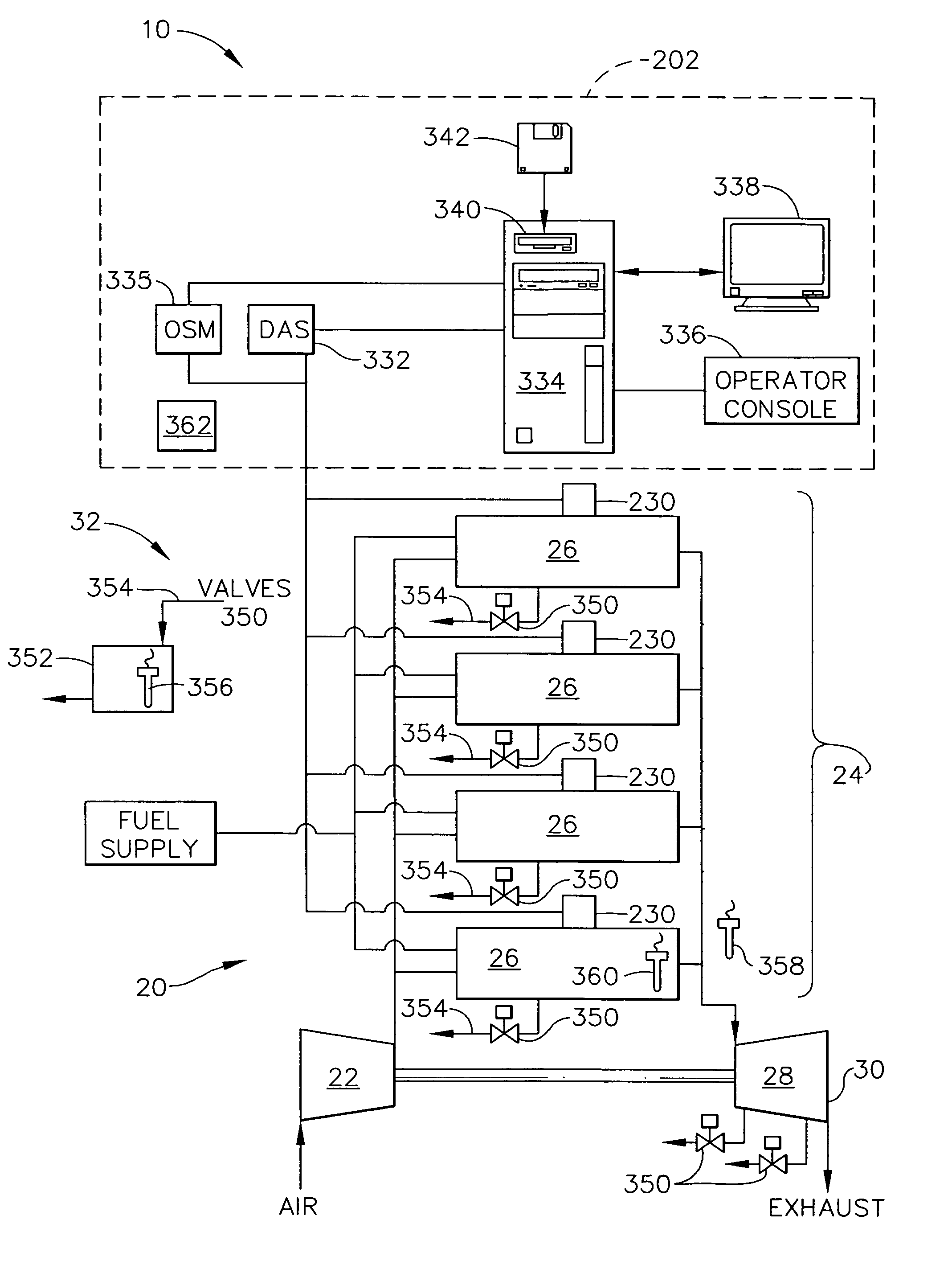
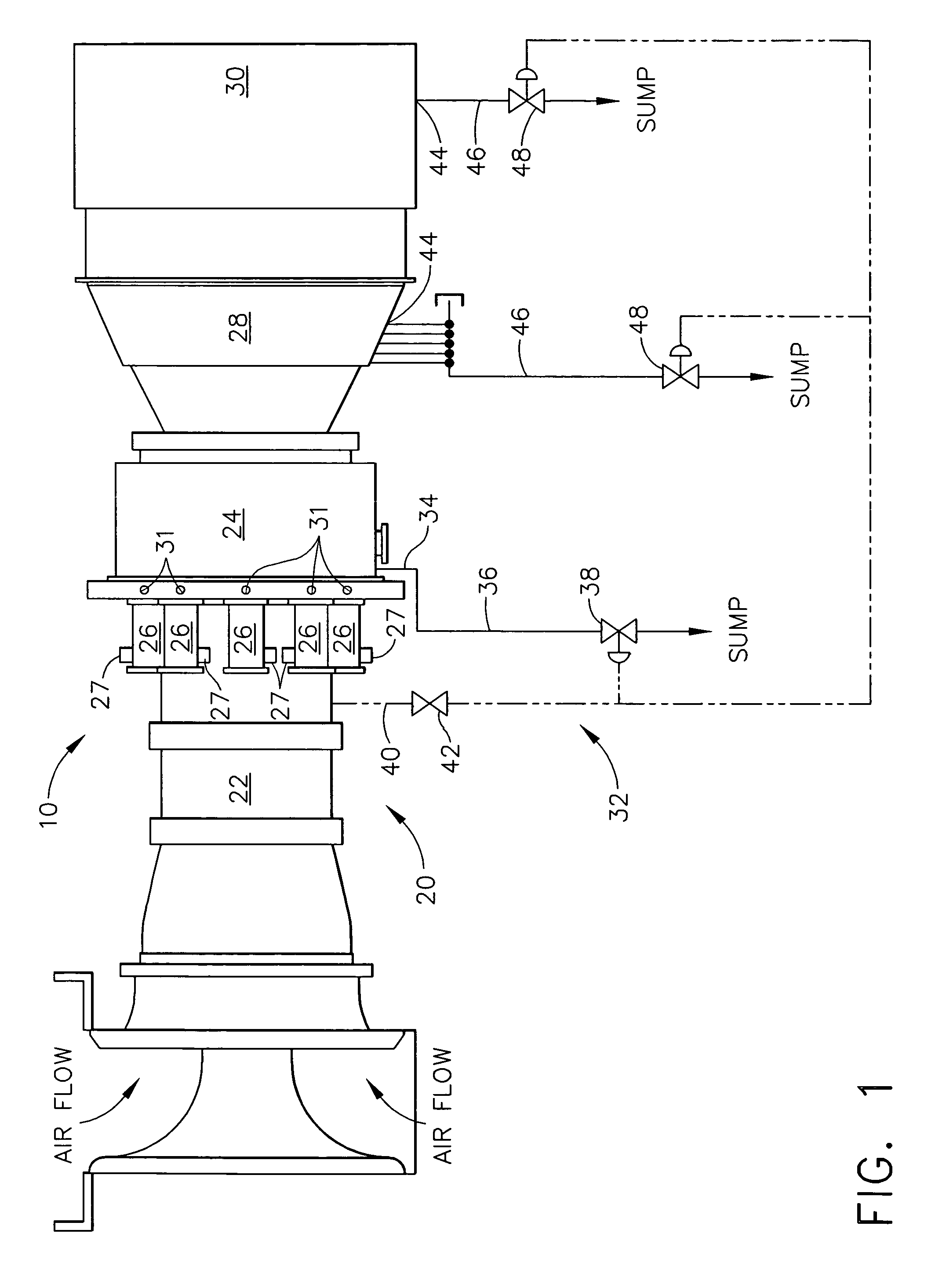
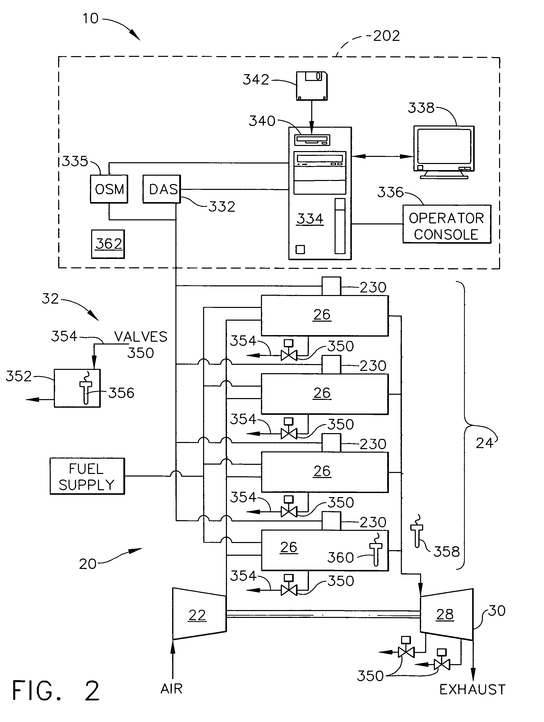
[0011]FIG. 1 is a side view of a gas turbine system 10 that includes a gas turbine engine 20. Gas turbine engine 20 includes a compressor section 22, a combustor section 24 including a plurality of combustor cans 26 and an associated ignition system 27, and a turbine section 28 coupled to compressor section 22 via a shaft (not...


PUM


Abstract

A method of operating a gas turbine engine is provided. The method includes introducing a fuel into a combustor, detecting a failure of ignition of the fuel, and preventing ignition until the introduced fuel is substantially removed from the gas turbine engine.

Description

BACKGROUND OF THE INVENTION[0001]This invention relates generally to gas turbine engines, and more particularly, to methods and systems for controlling the operation of gas turbine engines.[0002]At least some known gas turbine engines include a compressor section, a combustor section, and at least one turbine section. The compressor compresses air, which is mixed with fuel and channeled to the combustor. The mixture is then ignited generating hot combustion gases. The combustion gases are channeled to the turbine which extracts energy from the combustion gases for powering the compressor, as well as producing useful work to power a load, such as an electrical generator, or to propel an aircraft in flight.[0003]To start the engine, it is rotated to a predetermined speed, fuel is introduced, and an ignitor is energized. Sometimes the gas turbine engine fails to start properly, and / or the flame in the gas turbine engine may be inadvertently extinguished. In either case, some liquid fue...

Claims


Application Information

Patent Timeline
Patent Type & Authority Patents(United States)
IPC IPC(8): F02C7/00F02C9/46
CPCF02C7/26F02C9/26F02C9/36
Inventor RUNKLE, MARK ANDREWBACKMAN, STEVEN WILLIAMBLACK, PAUL DAVIDCOURNOYER, MARK ANDREWSPENGLER, KEVIN ANDREWMORRISON, DANIEL D.IASILLO, ROBERT JOSEPHMILLER, CHRISTOPHER DAVID
Owner GENERAL ELECTRIC CO
Why Eureka
Try Eureka