In-situ landfill gas well perforation method and apparatus

a landfill gas well and in-situ technology, applied in the direction of fluid removal, earth-moving drilling, wellbore/well accessories, etc., can solve the problems of reducing the amount of gas recovered or produced from a well, clogging of slots and perforations, time-consuming and expensive, etc., to increase gas recovery and increase gas recovery

Inactive Publication Date: 2008-06-17
WASTE MANAGEMENT INC
View PDF8 Cites 32 Cited by
  • Summary
  • Abstract
  • Description
  • Claims
  • Application Information

AI Technical Summary

Problems solved by technology

However, over time the slots and perforations become clogged as a result of the formation of precipitates and biological films in the well.
Consequently, the amount of gas recovered or produced from a well may decrease over time.
Another problem with the gas well piping is that it is often installed as the landfill lifts are created.
However, this is time consuming and expensive.

Method used


Image

  • In-situ landfill gas well perforation method and apparatus
  • In-situ landfill gas well perforation method and apparatus

Examples


Embodiment Construction

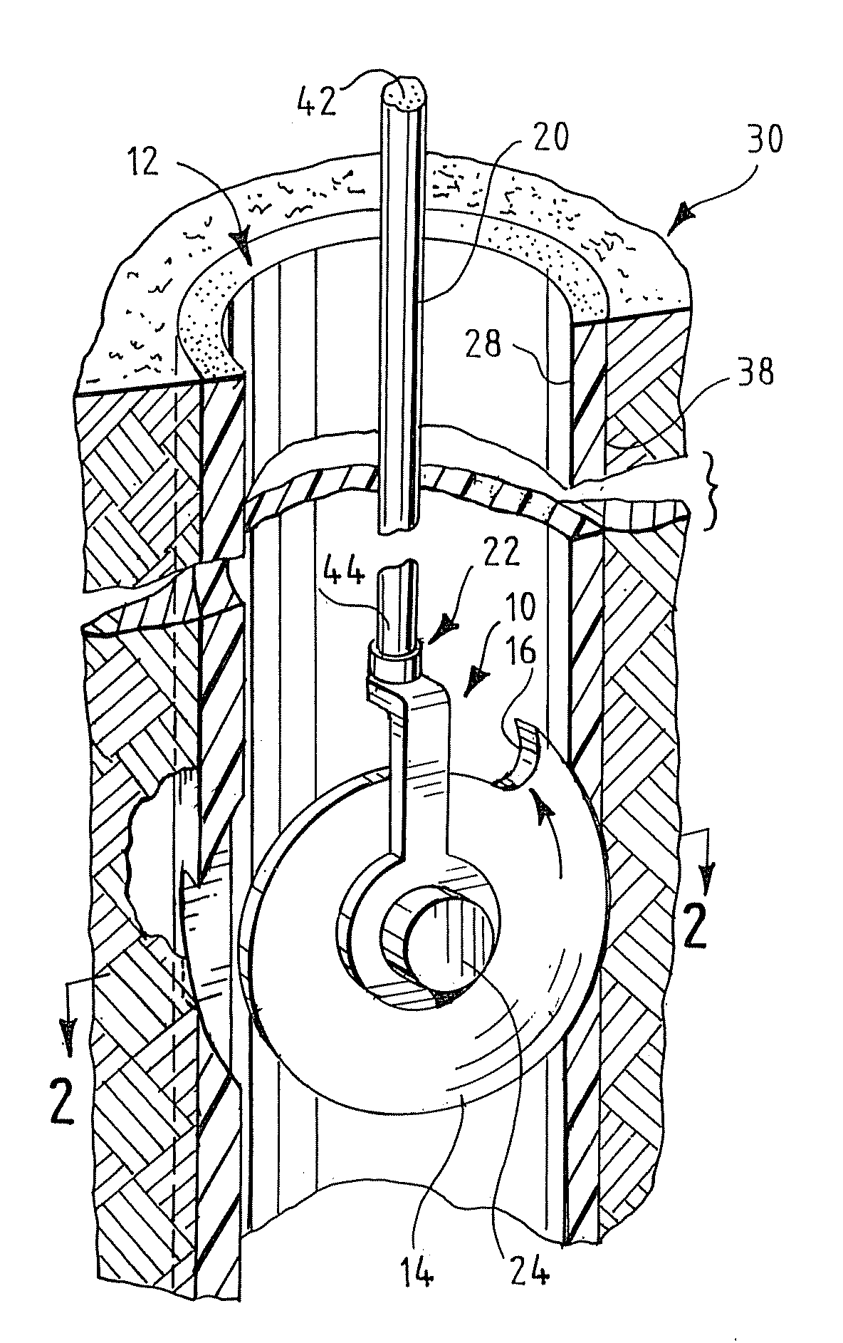
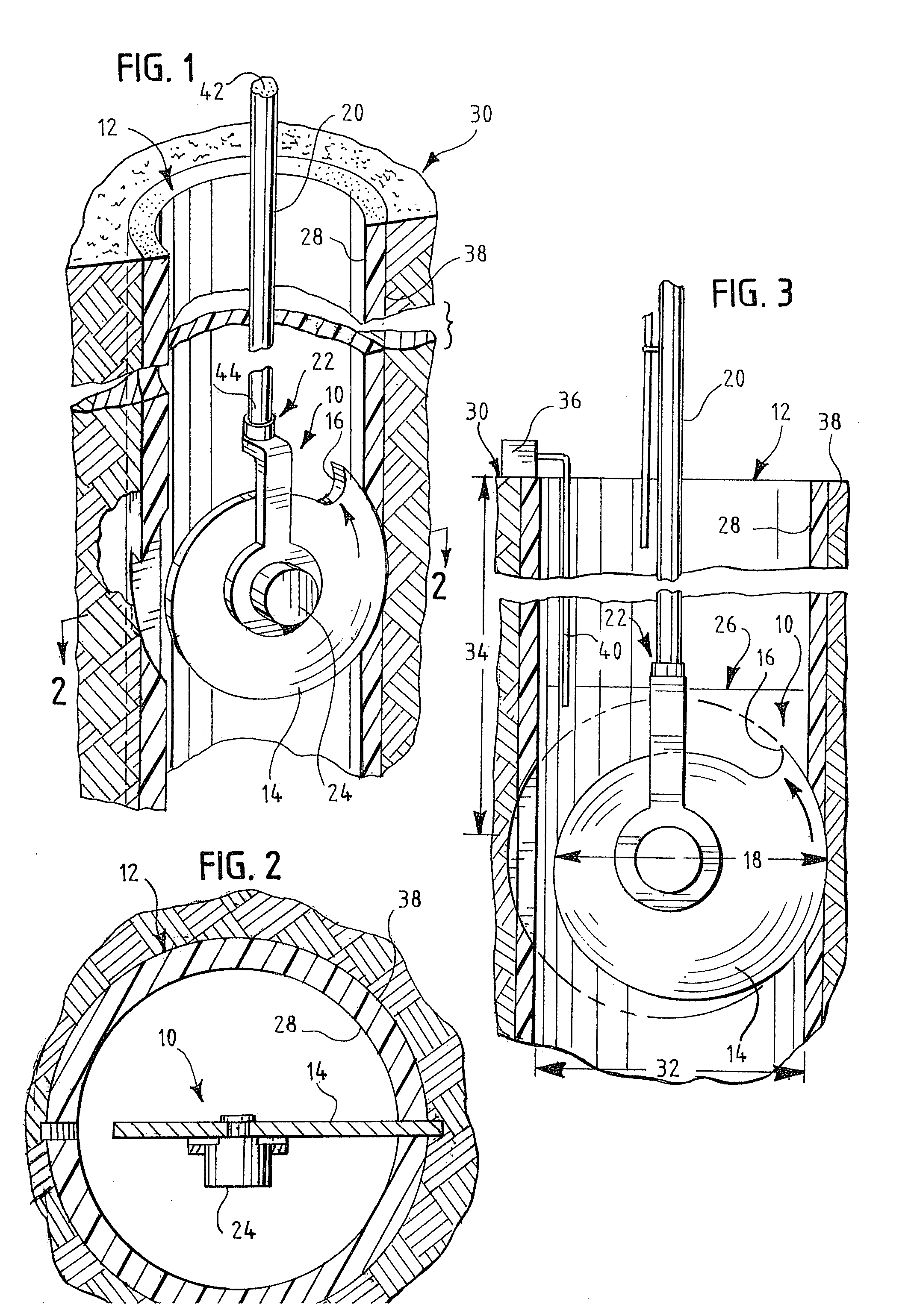
[0010]The invention provides a perforating device and method for perforating a landfill gas well in situ.

[0011]FIGS. 1 and 2 illustrate an embodiment of a perforating device 10 used to perforate a landfill gas well 12 in situ. Typically, gas well 12 is constructed of PVC, high-density polyethylene (HDPE) or other similar materials. Gas well 12 typically has an inner wall 28 and an outer wall 38. Gas well 12 has an effective inner diameter 32 ranging from about six to about twelve inches. Typically, effective inner diameter 32 is about eight inches. Perforating device 10 consists of at least one perforator 14 that has at least one cutting edge 16. Perforator 14 is made from a material that is able to perforate landfill gas wells, such as steel, and typically weighs one to three pounds or more. Perforating device 10 has a diameter 18 that is less than effective inner diameter 32 of gas well 12. For instance, diameter 18 of perforating device 10 is four inches, compared to an effective...


PUM


Abstract

The present invention relates to a method and apparatus for perforating a landfill gas well in situ. The invention allows for improved recovery of gas from a gas well without the danger of explosion.

Description

FIELD OF THE INVENTION[0001]The present invention relates to methods and devices for in situ perforation of landfill gas wells.BACKGROUND OF THE INVENTION[0002]The decomposition of waste in a landfill produces methane and other gaseous emissions. Landfill gas recovery wells are used to remove the gases from landfills. Removal of methane and other gases is both an environmental and a safety measure for preventing an accumulation of flammable gases. The gas wells typically consist of pipes made from PVC, high-density polyethylene (HDPE) and similar materials. The gas well's pipes are slotted or perforated to allow for recovery of the gases. However, over time the slots and perforations become clogged as a result of the formation of precipitates and biological films in the well. Consequently, the amount of gas recovered or produced from a well may decrease over time.[0003]Another problem with the gas well piping is that it is often installed as the landfill lifts are created. Consequen...

Claims


Application Information

Patent Timeline
Patent Type & Authority Patents(United States)
IPC IPC(8): E21B43/11
CPCE21B29/08E21B43/11
Inventor SEEGERS, RAYMONDMEYER, STEVE
Owner WASTE MANAGEMENT INC
Why Eureka
Try Eureka