Air guide structure in motor vehicle leg shield

a technology for leg shields and air guides, which is applied in the field of vehicle, can solve the problems of disadvantageous complexity of the structure of the leg shields, the disadvantageous structure of the wind guide members for guiding the cooling wind through the radiator, and the radiator (heat exchanger), and achieve the effect of simple structur

Inactive Publication Date: 2008-06-17
YAMAHA MOTOR CO LTD
View PDF10 Cites 32 Cited by
  • Summary
  • Abstract
  • Description
  • Claims
  • Application Information

AI Technical Summary

Benefits of technology

[0006]In order to overcome the problems described above, preferred embodiments of the present invention provide a vehicle having a much simpler structure for a wind guide that is arranged to guide air passing through a heat exchanger and a leg shield.
[0007]In addition, preferred embodiments of the present invention provide a vehicle that greatly improves the cooling capability of a heat exchanger.

Problems solved by technology

In the motorcycle disclosed in Japanese Patent Publication No. 3-48074, however, the pair of wind guide ducts must be provided independently of the leg shield, and hence the structure of a portion including a wind guide member for guiding the cooling wind passing through the radiator (heat exchanger) and the leg shield is disadvantageously complicated.
Further, the motorcycle disclosed in Japanese Patent Publication No. 3-48074 guides the cooling wind passing through the radiator to the wind guide ducts only through an air stream of the cooling wind, and hence it is difficult to guide a sufficient quantity of air to the wind guide ducts from behind the radiator.
Consequently, it is difficult to improve the cooling capability of the radiator (heat exchanger).

Method used


Image

  • Air guide structure in motor vehicle leg shield
  • Air guide structure in motor vehicle leg shield
  • Air guide structure in motor vehicle leg shield

Examples


first preferred embodiment

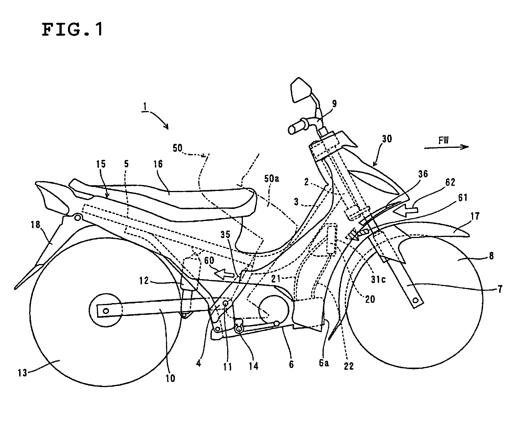
[0052]In the motorcycle 1 according to the first preferred embodiment, the front end of a mainframe 3 is connected to a head pipe 2, as shown in FIG. 1. The mainframe 3 is arranged to extend in a rearward direction as shown in FIG. 1. Rear arm brackets 4 and a seat rail 5 are connected to the rear end of the mainframe 3. The head pipe 2, the mainframe 3, the rear arm brackets 4 and the seat rail 5 constitute a body frame. An engine, preferably a water-cooled four-cycle engine 6, for example, is preferably mounted on the rear end of the mainframe 3 and the rear arm brackets 4. As can be understood, the water-cooled four-cycle engine 6 is just an example and other engines may be used. The engine 6 is arranged in a substantially horizontal manner and has a cylinder 6a disposed at a front portion thereof.

[0053]A front wheel 8 is rotatably mounted on the head pipe 2 through a front fork 7. A handle 9 is mounted on the head pipe 2. The handle 9 is used to steer by moving the front wheel 8...

second preferred embodiment

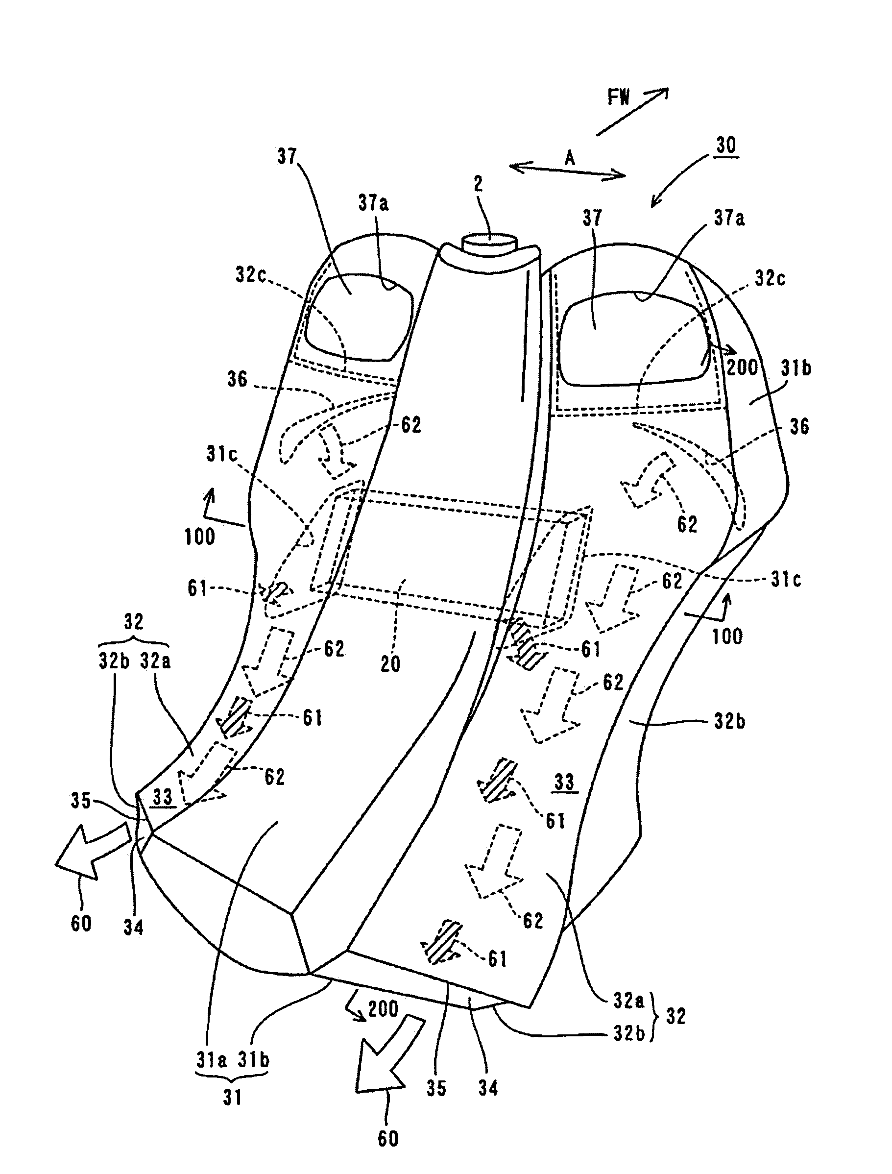
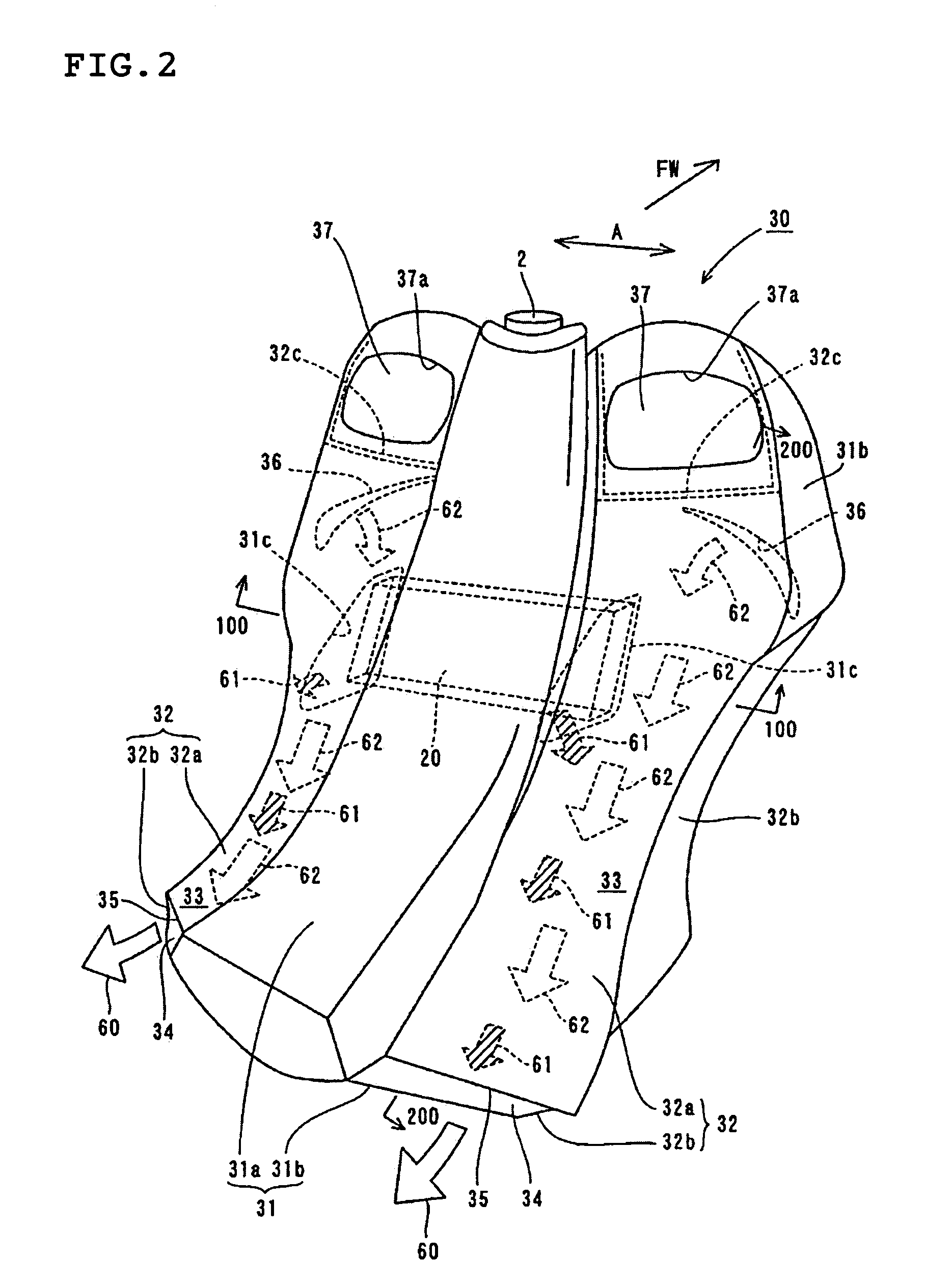
[0068]A second preferred embodiment of the present invention is now described with reference to FIGS. 8 to 12. The second preferred embodiment is described with reference to an example including a leg shield 130 having a structure that is different from that in the first preferred embodiment while providing ribs 131b and 131c projecting toward a radiator 20 on edges of openings 131a of the leg shield 130.

[0069]In a motorcycle 101 according to the second preferred embodiment shown in FIG. 8, the structures of portions other than the leg shield 130 are preferably similar to those of the motorcycle 1 according to the first preferred embodiment shown in FIG. 1. The leg shield 130 according to the second preferred embodiment preferably includes a pair of first cover members 131 spaced from each other by a predetermined distance extending along the lateral direction (direction A in FIGS. 9 and 10) of the motorcycle 101, a pair of second cover members 132 formed independently of the first ...


PUM


Abstract

A vehicle includes a leg shield arranged to cover the front sides of the legs of a driver riding the vehicle and a heat exchanger arranged on the front surface side of the leg shield. The leg shield includes a wind guide space formed by a wall member of the leg shield, a first opening formed in a portion of the wall member of the leg shield located at least behind the heat exchanger for guiding air passing through the heat exchanger to the wind guide space and a second opening formed in another portion of the wall member of the leg shield separated from the first opening by a predetermined distance for discharging the air passing through the heat exchanger, guided to the first opening from the wind guide space.

Description

BACKGROUND OF THE INVENTION[0001]1. Field of the Invention[0002]The present invention relates to a vehicle, and more particularly, the present invention relates to a vehicle including a heat exchanger such as a radiator.[0003]2. Description of the Related Art[0004]A motorcycle (vehicle) including a radiator (heat exchanger) for cooling a water-cooled four-cycle engine is generally known. Such a motorcycle is disclosed in Japanese Patent Publication No. 3-48074, for example. In this motorcycle disclosed in Japanese Patent Publication No. 3-48074, a radiator and a pair of wind guide ducts for guiding cooling wind passing through the radiator are arranged in a region between the front surface of a leg shield covering the front sides of the legs of a driver and a cover covering the front surface of the leg shield. When the motorcycle is in motion, running wind (cooling wind) is introduced from an opening of the cover for cooling the radiator, while the cooling wind passing through the r...

Claims


Application Information

Patent Timeline
Patent Type & Authority Patents(United States)
IPC IPC(8): B60K11/08B62D61/02B62J99/00B62J17/00
CPCB62J17/06F01P2050/16F01P3/18B62K2202/00B62J17/10
Inventor KONNO, TOSHIHIKOKAMIMURA, KAORUGUNAGUCHI, NAOTO
Owner YAMAHA MOTOR CO LTD
Why Eureka
Try Eureka