Image display system and method

a technology of image display and image, applied in the field of image display system and method, can solve the problems of significant light loss in the coupling between the illumination system and the light source assembly, and the system efficiency is significantly reduced, and achieve the effect of maximizing the amount of illumination

Inactive Publication Date: 2008-06-17
HEWLETT PACKARD DEV CO LP
View PDF23 Cites 7 Cited by
  • Summary
  • Abstract
  • Description
  • Claims
  • Application Information

AI Technical Summary

Benefits of technology

[0005]One aspect of the present invention provides an image display device. The device includes an image processing unit, a light source assembly, an optical modulator assembly, and a projection lens assembly. The image processing unit is configured to receive a video signal and generate image data and control signals. The light source assembly and optical modulator assembly are each controlled by the control signals such that the light source assembly generates illumination in a spatial distribution pattern that is coupled to optical modular assembly via a homogenizing device. The projection lens assembly is configured to project an image from the optical modulator assembly onto a viewing surface. The optical modular assembly is configured to maximize the amount of illumination coupled from the light source assembly, and includes at least one optical modulator surface configured to have a substantially 1:1 aspect ratio.

Problems solved by technology

In a typical system, significant light is lost in the coupling within the illumination system with regard to the light source assembly.
One of the reasons for this loss is geometric shape mismatch between the spatial distribution pattern of the light source and the collection of light by the illumination relay.
Hence, system efficiency is significantly reduced.

Method used


Image

  • Image display system and method
  • Image display system and method
  • Image display system and method

Examples


Embodiment Construction

[0009]In the following detailed description of the preferred embodiments, reference is made to the accompanying drawings which form a part hereof, and in which is shown by way of illustration specific embodiments in which the invention may be practiced. In this regard, directional terminology, such as “top,”“bottom,”“front,”“back,”“leading,”“trailing,” etc., is used with reference to the orientation of the Figure(s) being described. Because components of the present invention can be positioned in a number of different orientations, the directional terminology is used for purposes of illustration and is in no way limiting. It is to be understood that other embodiments may be utilized and structural or logical changes may be made without departing from the scope of the present invention. The following detailed description, therefore, is not to be taken in a limiting sense, and the scope of the present invention is defined by the appended claims.

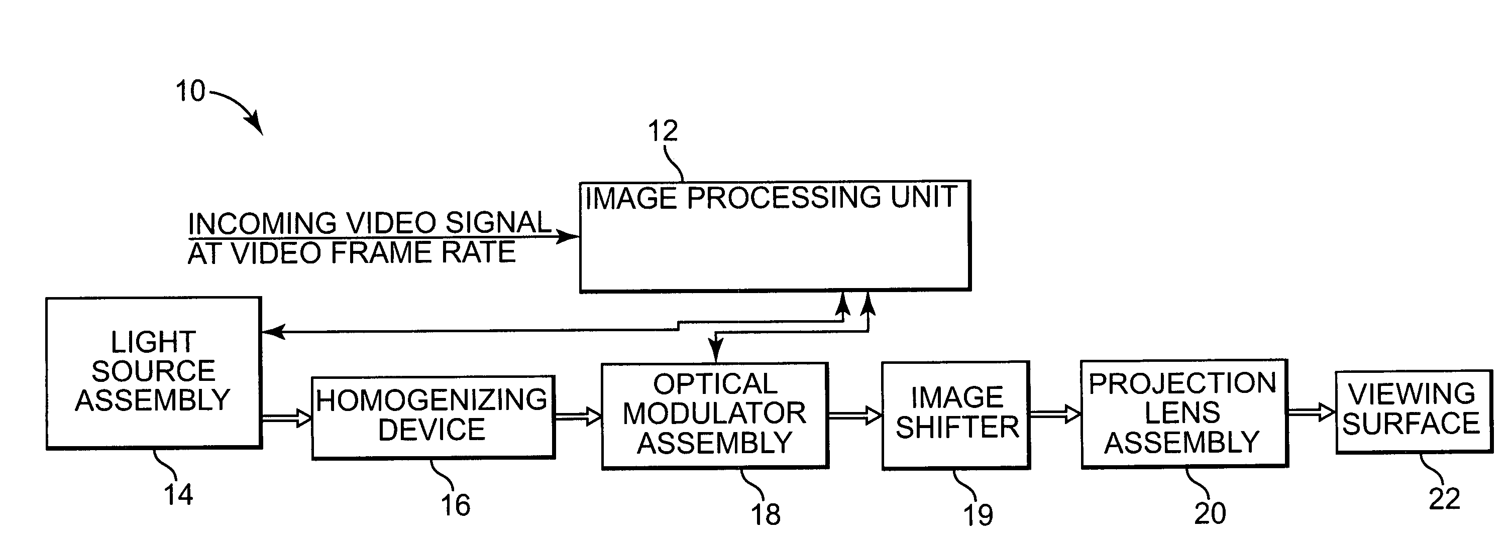
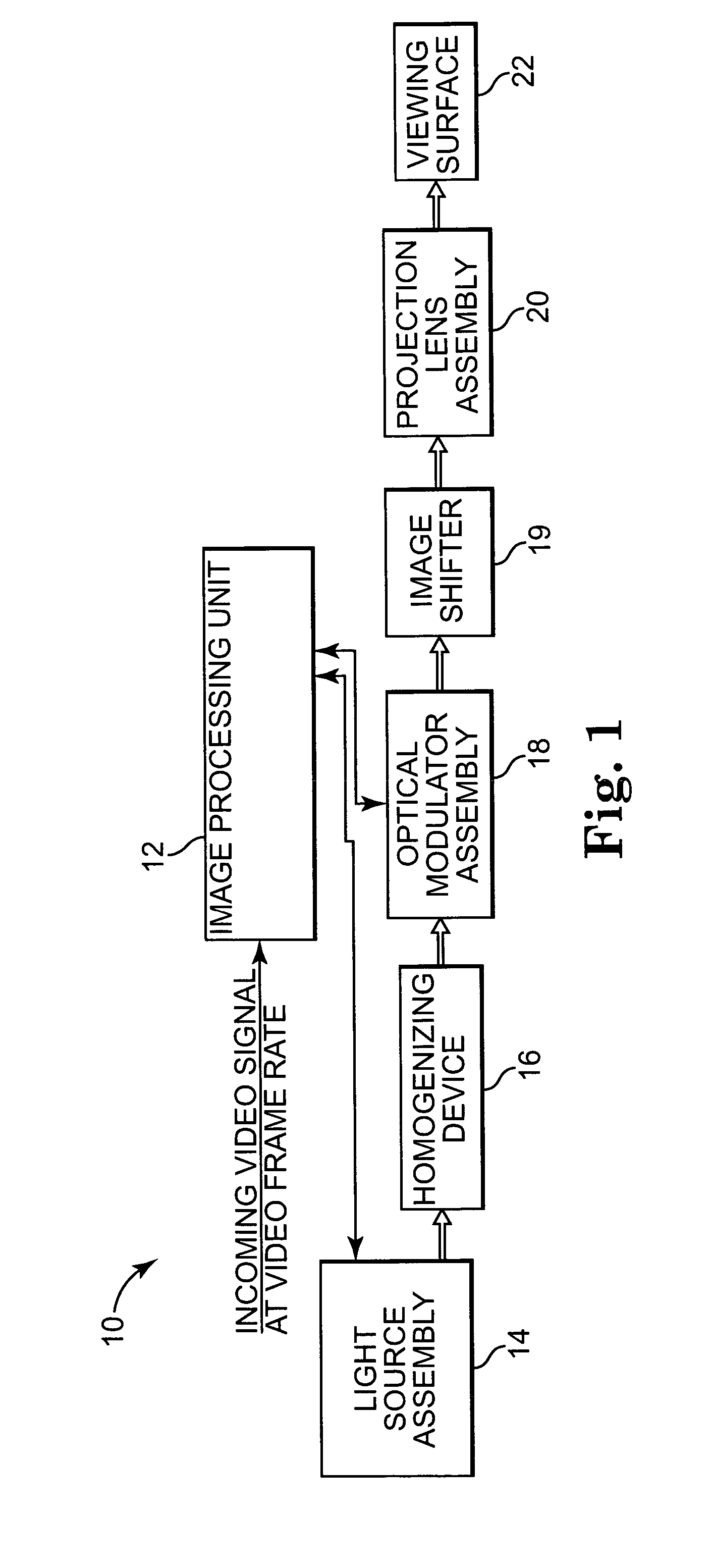
[0010]FIG. 1 illustrates one embodiment ...


PUM

PropertyMeasurementUnit
aspect ratioaaaaaaaaaa

Abstract

An image display device includes an image processing unit, a light source assembly, an optical modulator assembly, and a projection lens assembly. The image processing unit is configured to receive a video signal and generate image data and control signals. The light source assembly and optical modulator assembly are each controlled by the control signals such that the light source assembly generates illumination in a spatial distribution pattern that is coupled to optical modular assembly via a homogenizing device. The projection lens assembly is configured to project an image from the optical modulator assembly onto a viewing surface. The optical modular assembly is configured to maximize the amount of illumination coupled from the light source assembly, and includes at least one optical modulator surface configured to have a substantially 1:1 aspect ratio.

Description

BACKGROUND OF THE INVENTION[0001]Various techniques for displaying images exist. A typical digital projector has the following parts in order: Illumination system, optical modulator assembly and a projection lens system. A light source assembly is used by the illumination system to illuminate the optical modulator assembly and the projection lens system images the effective optical modulator surface on a screen.[0002]The illumination system typically consists of a light source assembly, color wheel, IR / UV filters, light source homogenizer, and an illumination relay made up of lenses / mirrors. An optical modulator assembly can consist of one or more optical modulators such as (DMD, LCos, LCD etc.). When certain optical modulator assemblies and the light source assemblies are used, a color wheel and IR / UV filters can be omitted depending upon the design architecture. A projection lens system typically consists of lenses and mirrors.[0003]A light source assembly typically consists of on...

Claims


Application Information

Patent Timeline
Patent Type & Authority Patents(United States)
IPC IPC(8): G03B21/26F21V7/04G02B13/08G02B26/08G02F1/1335G03B21/20G03H1/00H04N11/20H04N5/46H04N5/70H04N5/74H04N7/01
CPCG03B21/26
Inventor GUPTA, ANURAGERICKSON, DAVID L.LERNER, SCOTT A
Owner HEWLETT PACKARD DEV CO LP
Why Eureka
Try Eureka