Delay locked loop with a function for implementing locking operation periodically during power down mode and locking operation method of the same

a technology of locking operation and lock loop, which is applied in the direction of electrical equipment, automatic control, etc., can solve the problems of reducing the operation speed of the semiconductor device, increasing the power consumed by the dll, and increasing the consumption of the semiconductor device. , to achieve the effect of reducing the consumption power, fast speed and reducing the phase differen

Active Publication Date: 2008-06-17
SK HYNIX INC
View PDF14 Cites 58 Cited by
  • Summary
  • Abstract
  • Description
  • Claims
  • Application Information

AI Technical Summary

Benefits of technology

[0005]The present invention is directed to a DLL capable of decreasing a consumed power during a power down mode and operating at a fast speed in a normal operation after the power down mode by being periodically enabled during the power down mode to carry out a locking operation, thereby decreasing a phase difference between an external clock signal and an internal clock signal.
[0006]The present invention is also directed to a locking operation method of a DLL capable of decreasing a consumed power during a power down mode and operating at a fast speed in a normal operation after the power down mode by periodically being enabled during the power down mode to carry out a locking operation, thereby decreasing a phase difference between an external clock signal and an internal clock signal.
[0009]Another aspect the present invention is to provide a DLL, which includes a global clock generator, a clock delay unit, and a power down control unit. The global clock generator generates first to N (N is an integer) global clock signals based on an input clock signal. The clock delay unit operates in synchronization with some of the first to N global clock signals, compares a phase of the input clock signal with a phase of each of first and second reference clock signals generated based on the input clock signal, outputs a phase detection signal in accordance with the comparison, delays the input clock signal by a predetermined time, and corrects a duty ratio of the delayed input clock signal to output a corrected clock signal. The power down control unit outputs the input clock signal to both of the global clock generator and the clock delay unit in response to some of the global clock signals, the phase detection signal, and a power down signal.

Problems solved by technology

Meanwhile, the DLL includes a plurality of delay units which consume a relatively large amount of currents, so that its consumed power increases at the time of locking operation of the DLL.
Accordingly, in the case of the semiconductor device including the DLL, the consumed power of the DLL takes up a relatively large amount of the total consumed power of the semiconductor device.
As such, when the locking operation time of the DLL increases, an operational speed of the semiconductor device decreases, and an operational performance of the semiconductor device is degraded.
Such a phenomenon may be more severe when the time taken for maintaining the semiconductor device in the power down mode increases (i.e., when the time taken for disabling the DLL increases).
However, when the DLL is continuously enabled, the consumed power of the DLL increases, so that the total consumed power of the semiconductor device increases.

Method used


Image

  • Delay locked loop with a function for implementing locking operation periodically during power down mode and locking operation method of the same
  • Delay locked loop with a function for implementing locking operation periodically during power down mode and locking operation method of the same
  • Delay locked loop with a function for implementing locking operation periodically during power down mode and locking operation method of the same

Examples


Embodiment Construction

[0023]Preferred embodiments of the present invention will be described below in more detail with reference to the accompanying drawings. The present invention may, however, be embodied in different forms and should not be constructed as limited to the embodiments set forth herein. Rather, these embodiments are provided so that this disclosure will be thorough and complete, and will fully convey the scope of the invention to those skilled in the art. Like numerals refer to like elements throughout the specification.

[0024]Hereinafter, it will be described about an exemplary embodiment of the present invention in conjunction with the accompanying drawings.

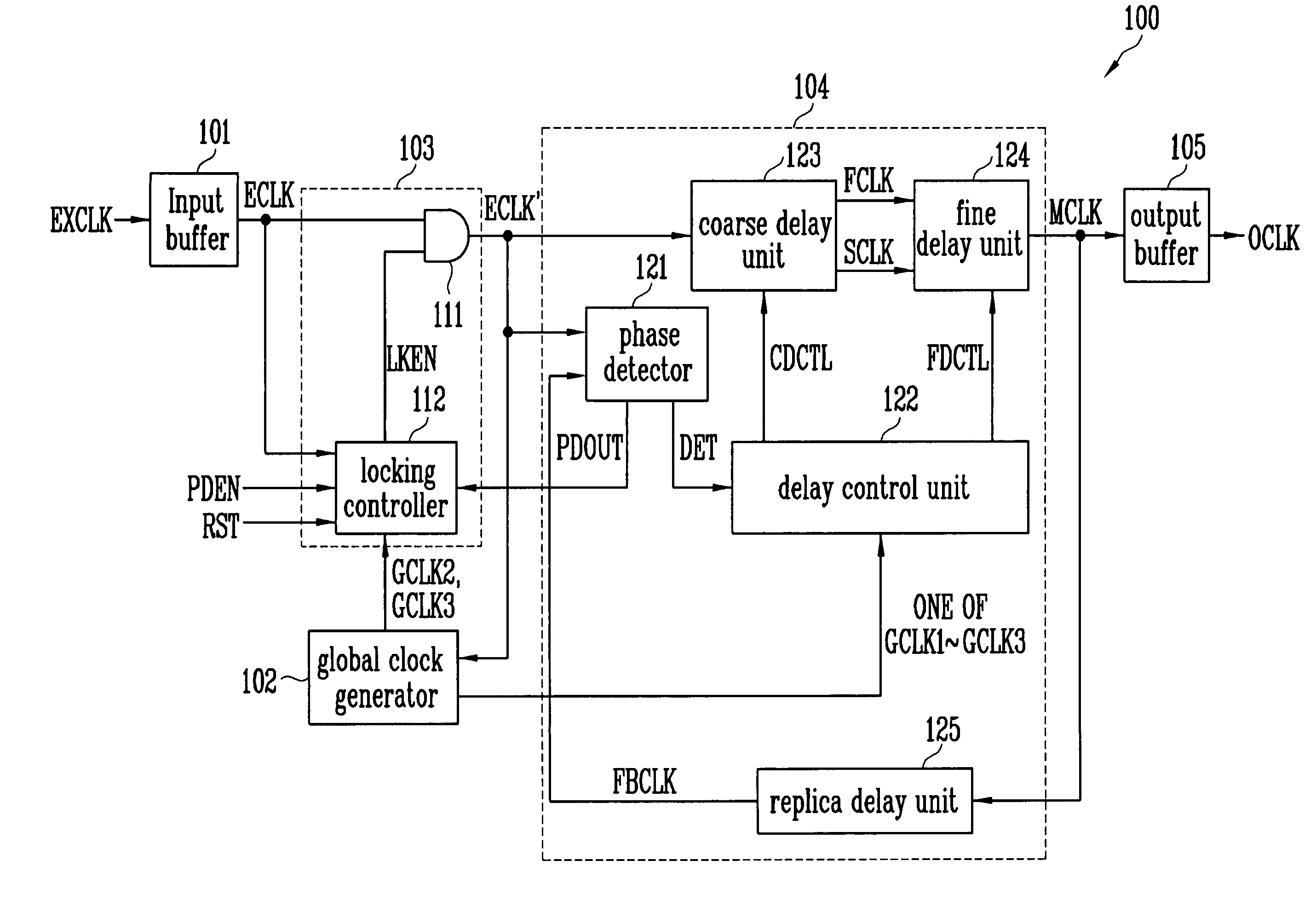
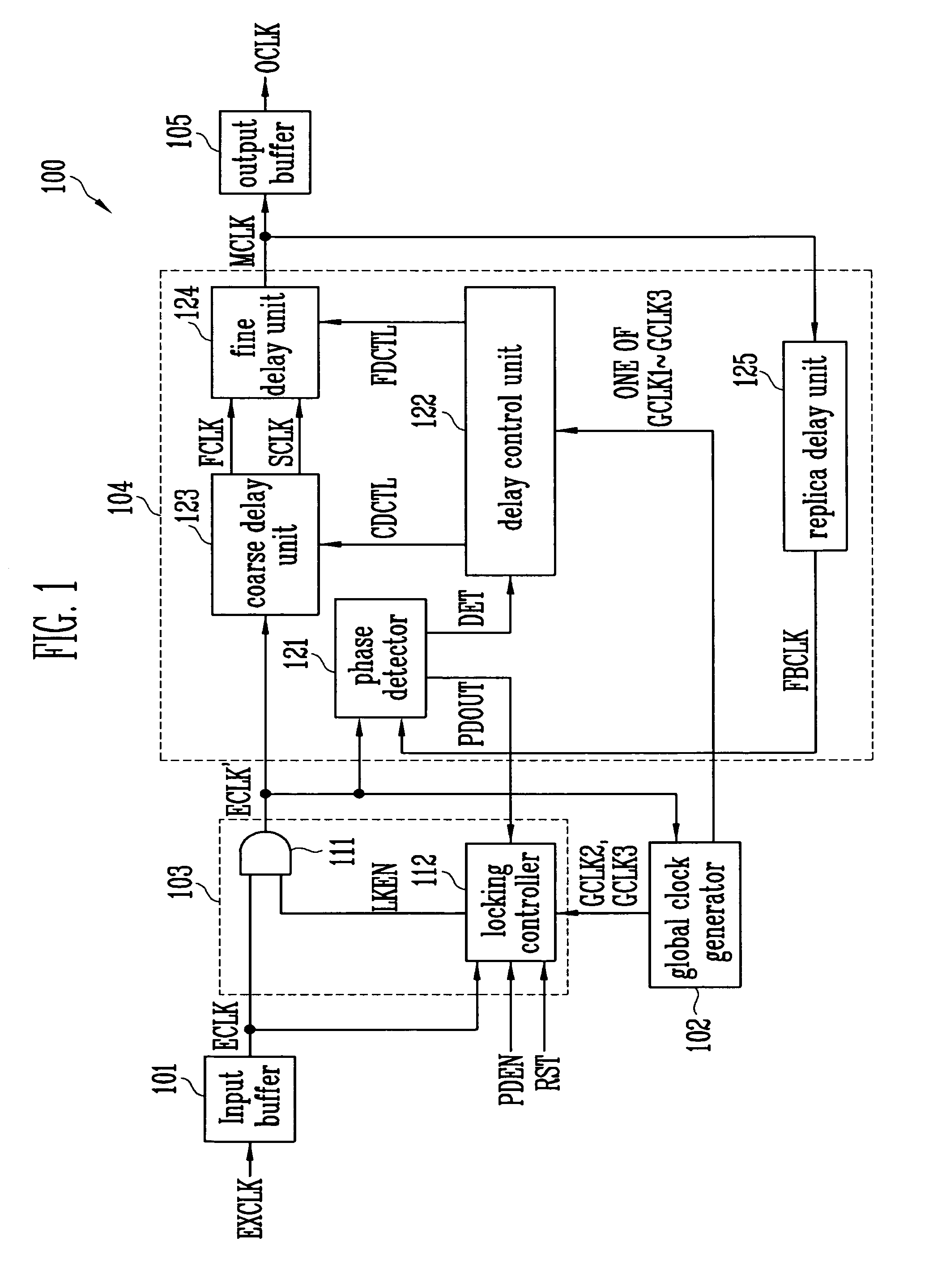
[0025]FIG. 1 is a block diagram schematically illustrating the DLL in accordance with an embodiment of the present invention. Referring to FIG. 1, the DLL 100 includes an input buffer 101, a global clock generator 102, a power down control unit 103, a clock delay unit 104, and an output buffer 105. The input buffer 101 receives an ext...


PUM


Abstract

A Delay Locked Loop (DLL) having a function of periodically executing a locking operation during a power down mode and a locking operation method of the same, which includes a global clock generator, a clock delay unit, and a power down control unit. The power down control unit, in response to some of a plurality of global clock signals, a phase detection signal, and a power down signal, outputs an input clock signal to each of the global clock generator and the clock delay unit. During the power down mode, the clock delay unit is enabled to periodically carry out the locking operation whenever it receives the input clock signal. Therefore, a consumed power of the DLL can be decreased during the power down mode, and a phase difference between an external clock signal and an internal clock signal during the power down mode can be decreased by the periodical locking operation of the clock delay unit, so that the DLL can operate at a fast speed after the power down mode.

Description

BACKGROUND[0001]1. Field of the Invention[0002]The present invention relates to a semiconductor device and more particularly, to a Delay Locked Loop (DLL) generating an internal clock signal.[0003]2. Discussion of Related Art[0004]In general, mobile products such as camcorders, digital cameras, cell phones, MP3 (MPEG-1 Layer3) players, or the like should operate for a long time with a low power, so that consumed powers of the semiconductor devices included in the mobile products should be decreased. Meanwhile, the DLL includes a plurality of delay units which consume a relatively large amount of currents, so that its consumed power increases at the time of locking operation of the DLL. Accordingly, in the case of the semiconductor device including the DLL, the consumed power of the DLL takes up a relatively large amount of the total consumed power of the semiconductor device. Consequently, when the consumed power of the DLL decreases, the total consumed power of the semiconductor de...

Claims


Application Information

Patent Timeline
Patent Type & Authority Patents(United States)
IPC IPC(8): H03L7/06
CPCH03L7/07H03L7/0805H03L7/0818H03L7/087H03L7/095H03L7/0814H03L7/0816H03L7/081H03L7/08
Inventor LEE, HYUN WOO
Owner SK HYNIX INC
Why Eureka
Try Eureka