
Dynamic identification and correction of defective pixels

a dynamic identification and correction technology, applied in the field of image sensors, can solve the problems of further testing of given pixels, considered to be defective, etc., and achieve the effect of reducing the complexity and cost of the device, and eliminating the time-consuming and costly calibration process to define the location of defective pixels

Inactive Publication Date: 2008-06-17
QUALCOMM INC
View PDF15 Cites 14 Cited by
  • Summary
  • Abstract
  • Description
  • Claims
  • Application Information

AI Technical Summary

Benefits of technology

The present invention relates to identifying and correcting defective pixels in a sensor, such as a camera sensor, in real-time as the sensor is being used. This eliminates the need for a separate defective pixel table and reduces the complexity and cost of the device. The process involves testing each pixel individually while exposing it to an image field with variations in intensity and color. The output of each pixel is measured and compared with neighboring pixels to determine if it is good or defective. The defective pixels are then corrected based on the surrounding pixels. The invention also includes calculating thresholds for identifying defective pixels based on the distribution of pixel outputs and adapting the thresholds to changes in the sensor or imaging optics. Overall, the invention simplifies the process of identifying and correcting defective pixels in sensors and improves the quality of captured images.

Problems solved by technology

But if the differences are all positive or all negative, the given pixel is considered to possibly be defective and is tested further.

Method used


Image

  • Dynamic identification and correction of defective pixels
  • Dynamic identification and correction of defective pixels
  • Dynamic identification and correction of defective pixels

Examples


Embodiment Construction

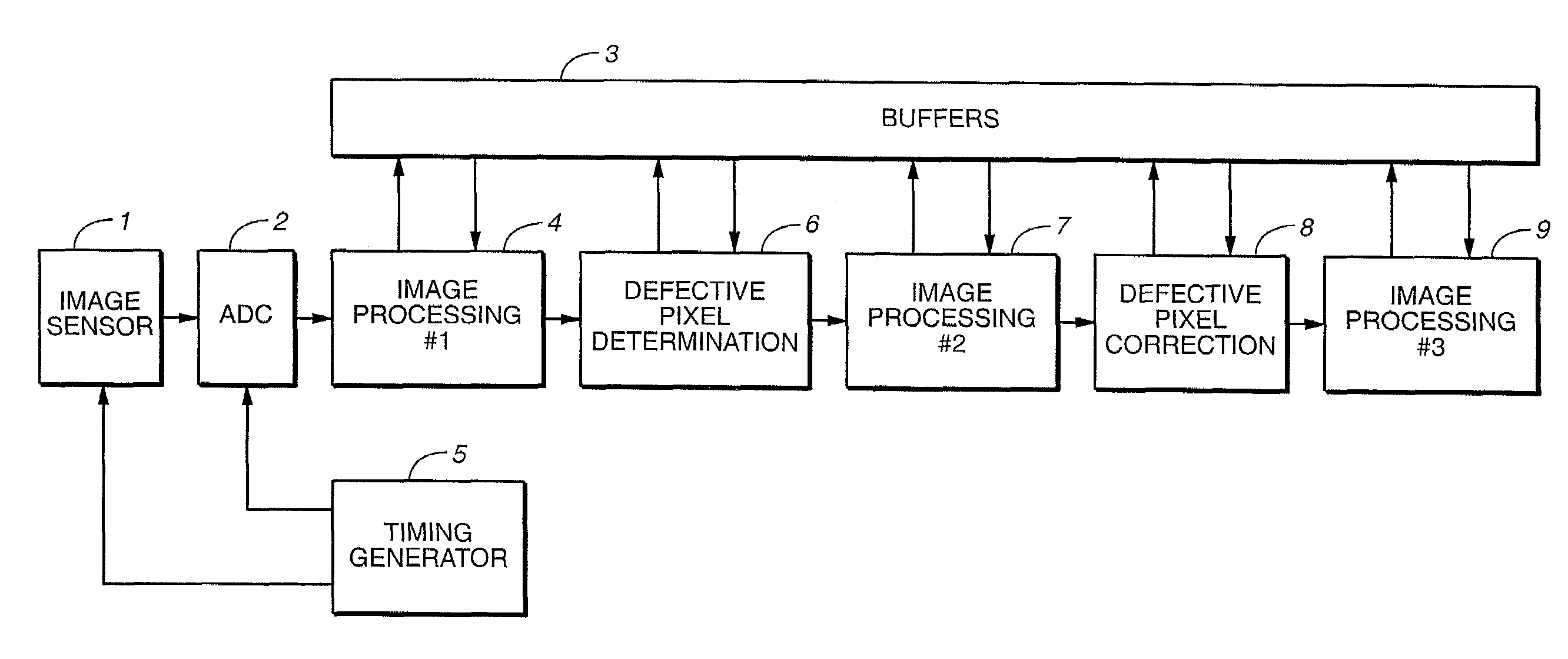
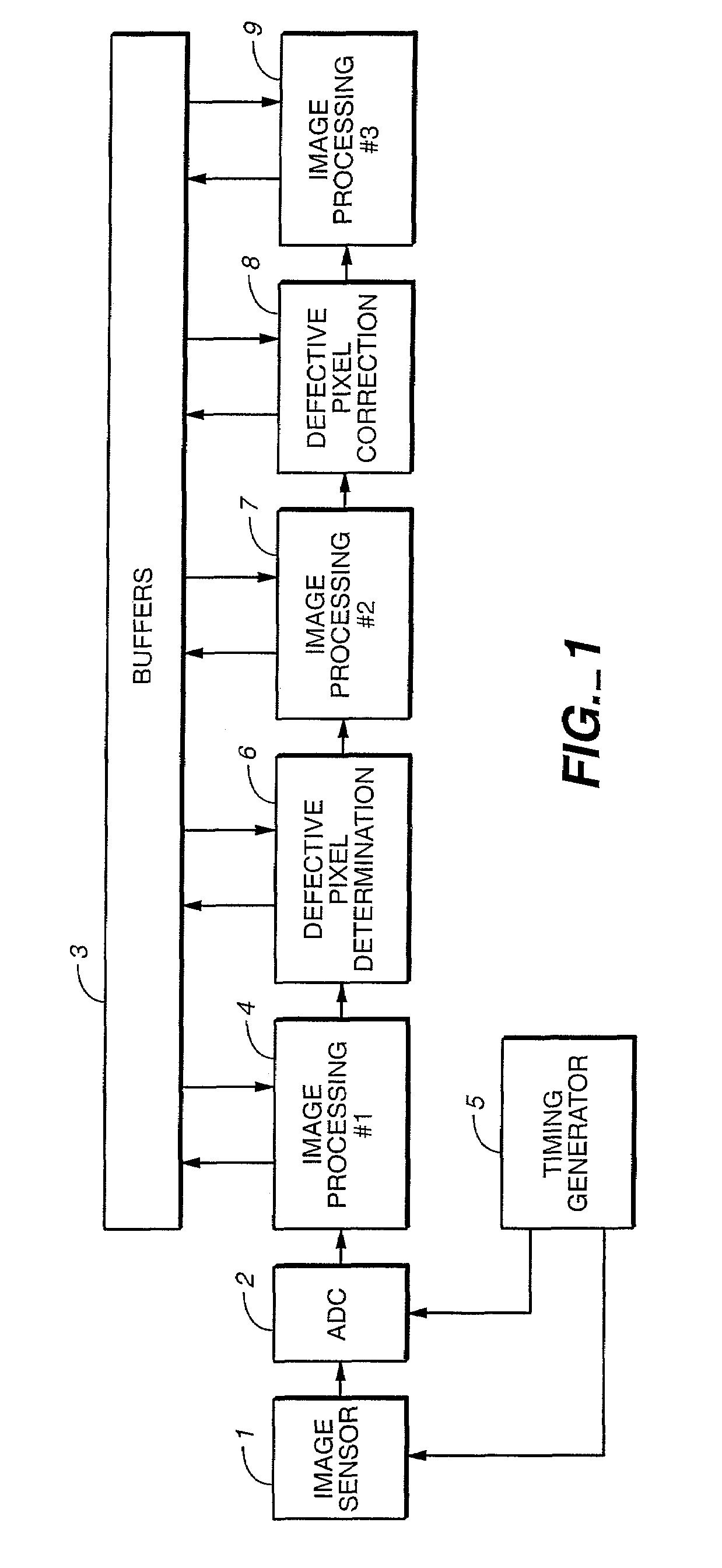
[0013]As depicted in FIG. 1, a camera includes an image sensor 1 that provides analog signals proportional to the light impinging on the sensor. The sensor signal is connected to an analog-to-digital converter (ADC) 2, which translates the sensor analog signals into digital signals. A timing generator 5 controls operation of the sensor 1 and the ADC 2. The digitized sensor output data then go through a chain of processing stages. Two of these stages are defective pixel determination 6, which identifies defective pixels, and defective pixel correction 8, which corrects a located defective pixel from outputs of pixels neighboring the identified defective pixel. Image processing stages 4, 7 or 9 may or may not be included. Each one of the processing chain stages can use the buffer 3 to pass the processed image data to succeeding stages, and can employ the buffers 3 for temporary storage of data created as part of the processing performed. The camera also includes an optical system (not...


PUM


Abstract

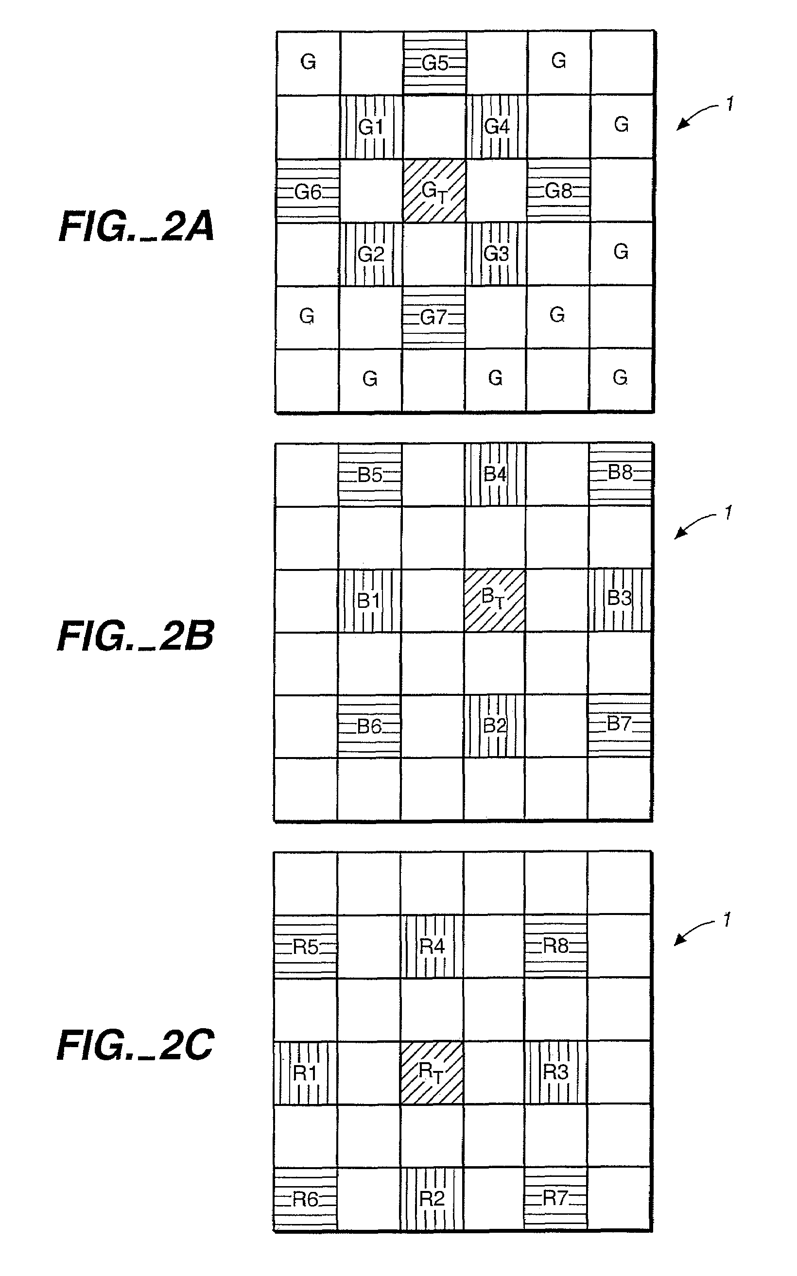
Rather than storing a table within a digital camera or other optical device of defective pixels within its image sensor, defective pixels are dynamically identified by comparing the output values of individual pixels under test with those of neighboring pixels. If the neighbors are all above or below the pixel under test by a defined threshold amount, the output of the pixel under test is replaced with a value calculated from the outputs of neighboring pixels.

Description

FIELD OF THE INVENTION[0001]This invention relates generally to image sensors having a two-dimensional array of photo-detector pixel elements, and, more specifically, to techniques for identifying individual defective pixels and generating signals in place of those of the defective pixels.BACKGROUND[0002]Image sensors with an increasing number of image sensing photo-detector elements are being used in digital cameras designed to be sold in large quantities to consumers. Although such cameras most commonly utilize sensors having from 2 to 4 megapixels at the present time, it is not uncommon to find digital cameras available that employ image sensors as large as large as 5 to 6 megapixels. And this number will likely increase in the future. Normally, not all the light sensing elements in these sensors work correctly; some are defective. Defective light sensing elements do not react to light properly, and thus distort a resulting image. In some cases, one or more light sensing elements...

Claims


Application Information

Patent Timeline
Patent Type & Authority Patents(United States)
IPC IPC(8): H04N9/64H04N5/367H04N5/369
CPCH04N9/045H04N17/002H04N5/3675H04N25/683H04N23/843H04N25/134
Inventor PINTO, VICTORSHAPOSHNIK, DIANA
Owner QUALCOMM INC
Learn More