System and method for optically powering a remote network component

a technology of optical network and remote network component, which is applied in the field of system and method for optical network remote network component powering, can solve the problems of disadvantage, high cost, and difficulty in adding such power lines, and achieve the effects of enhancing the reliability of the resulting network, low cost, and easy operation

Active Publication Date: 2008-06-17
CORNING INC
View PDF4 Cites 121 Cited by
  • Summary
  • Abstract
  • Description
  • Claims
  • Application Information

AI Technical Summary

Benefits of technology

[0009]The use of VCSELs biased by electrical power generated by remotely-located optical power sources provides a number of advantages over the prior art. Unlike EAMs, VCSELs are low cost and compatible with both multi-mode and single mode optical fibers. They are easily operated by the amount of power that typically can be transmitted through optical fibers. Additionally, VCSELs may be fabricated to operate within any of the wavelengths currently in use in optical networks, including the 0.85, 1.3, and 1.55 micrometer wavelengths used in high speed networks. Finally, the conversion of optical power provides clean, spike-free electrical power that is immune from electromagnetic and radio frequency interference, thereby enhancing the reliability of the resulting network.

Problems solved by technology

However, the remote location of the added components often makes the addition of such power lines difficult and expensive.
Unfortunately, EAMs are relatively expensive, being manufactured in small numbers.
Hence, such a solution again requires (in most cases) the replacement of at least some optical fiber of the system, and is disadvantageously expensive due to the cost of EAMs.

Method used


Image

  • System and method for optically powering a remote network component
  • System and method for optically powering a remote network component
  • System and method for optically powering a remote network component

Examples


Embodiment Construction

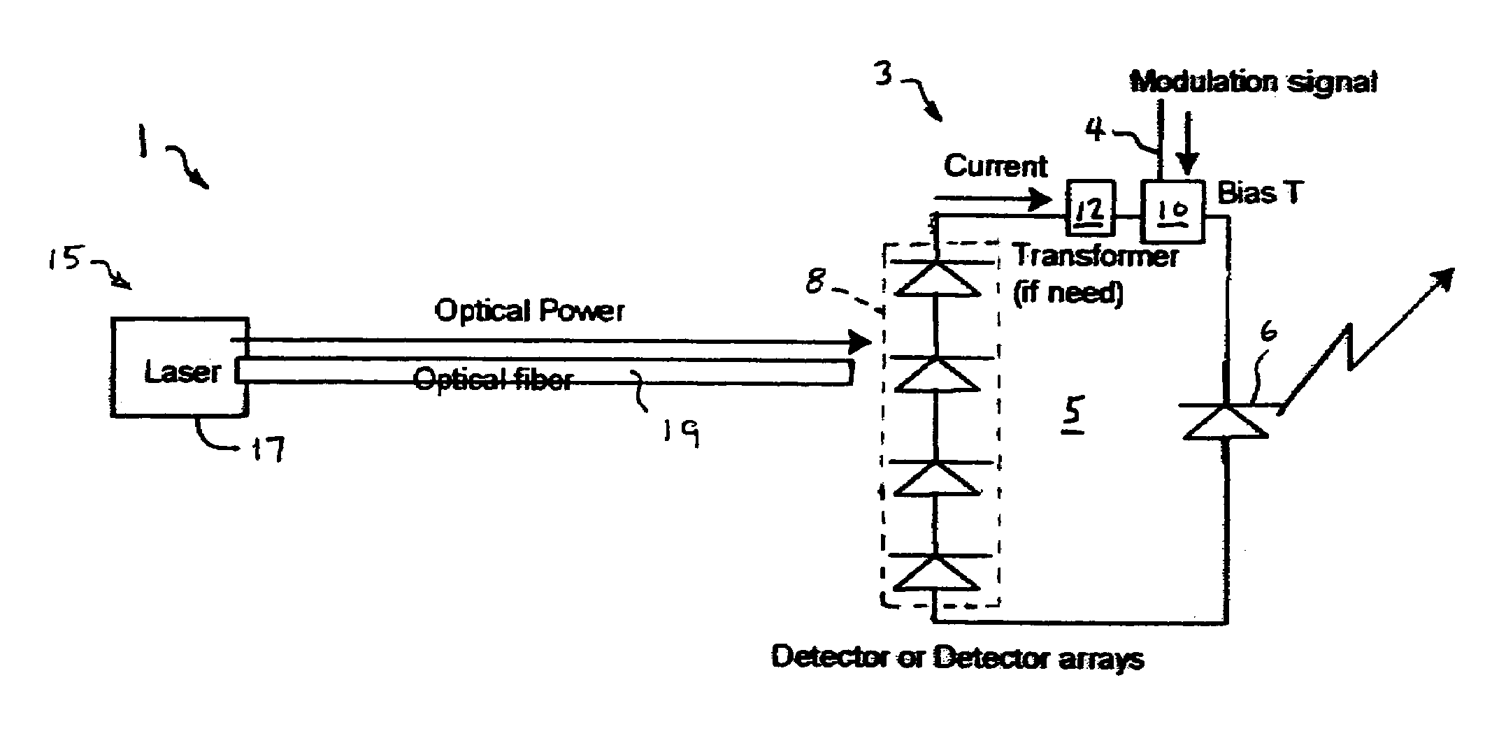
[0018]With reference now to FIG. 1, wherein like numbers designate like components throughout all the several figures, the system 1 of the invention includes a remote component 3 of a network (not shown) that processes an input signal. The remote component 3 includes input signal source 4 connected to a circuit 5 that includes a VCSEL 6, a photodetector array 8 and a bias tee 10. A DC transformer 12 may also be included in the circuit 5 to adjust the voltage versus amperage of the power generated by the photodetector array 8 in order to maximize the photonic output of the VCSEL 6. Accordingly, the use of such a component is generally not preferred.

[0019]The system 1 further includes a remote optical power source 15 which in the example of FIG. 1 is formed by a laser light source 17 having an output connected to an optical fiber 19. Fiber 19 in turn is optically coupled to the photodetector array 8. The optical power source 17 may be formed from any one of a number of commercially-av...


PUM


Abstract

Both a system and method for optically powering a network component, such as the transponder of a picocell, is provided. The system includes a vertical cavity surface emitting laser (VCSEL) for processing an input signal, a remotely-located optical power source, and an optical fiber for conducting optical power from the source to the VCSEL. The VCSEL may be electrically biased from current generated by an optical-electro converter coupled to the fiber, or directly optically biased from light from the optical power source. A bias tee is connected between an input signal and an input of the VCSEL such that the VCSEL generates a modulated optical signal. The system may be the transponder of a picocell system where the VCSEL generates an optical uplink signal conducted to a head-end circuit via the same or a separate optical fiber.

Description

FIELD OF THE INVENTION[0001]This invention generally relates to a system and method for optically powering a remotely located component of an optical network, and is specifically concerned with the use of a photo detector array to convert optical power delivered from a remotely located source into electrical power to bias a vertical cavity surface emitting laser (VCSEL) to process an input signal.BACKGROUND OF THE INVENTION[0002]Optical networks are presently in use in many buildings. Despite their inherently high bandwidth capacity relative to systems based on electrical cables, such networks must often be expanded to keep up with the ever increasing bandwidth demands of improved computer and telecommunications systems. Network expansion typically involves the addition of network components that are remotely located from the central processing unit of the network. In particular, the growth of wireless communication has increased the demand for wireless interfaces with existing offi...

Claims


Application Information

Patent Timeline
Patent Type & Authority Patents(United States)
IPC IPC(8): H01S3/00H04B10/43
CPCH04B10/807
Inventor NISHIYAMA, NOBUHIKOSAUER, MICHAELZAH, CHUNG-EN
Owner CORNING INC
Why Eureka
Try Eureka