Long instruction word controlling plural independent processor operations

a technology of independent processors and long instruction words, applied in the direction of program control, computation using denominational number representations, instruments, etc., can solve the problems of loading the computational capacity of the system processor, the computer system processor is not particularly designed for handling bit mapped graphics, and the design choices that are very reasonable for general purpose computing are unsuitable for bit mapped graphics systems

Inactive Publication Date: 2008-06-17
TEXAS INSTR INC
View PDF2 Cites 28 Cited by
  • Summary
  • Abstract
  • Description
  • Claims
  • Application Information

AI Technical Summary

Problems solved by technology

First, the computer system processor was not particularly designed for handling bit mapped graphics.
Design choices that are very reasonable for general purpose computing are unsuitable for bit mapped graphics systems.
In addition, it was quickly discovered that the processing needed for image manipulation of bit mapped graphics was so loading the computational capacity of the system processor that other operations were also slowed.
However, a useful graphics computer system often requires many functions besides those few that are implemented in such a hardware graphics controller.
Typically these hardware graphics controllers allow the system processor only limited access to the bit map memory, thereby limiting the degree to which system software can augment the fixed set of functions of the hardware graphics controller.
Each of these fields presents unique problems, but image data compression and decompression are common themes.
The amount of transmission bandwidth and the amount of storage capacity required for images and particular full motion video is enormous.
Without efficient video compression and decompression that result in acceptable final image quality, these applications will be limited by the costs associated with transmission bandwidth and storage capacity.

Method used


Image

  • Long instruction word controlling plural independent processor operations
  • Long instruction word controlling plural independent processor operations
  • Long instruction word controlling plural independent processor operations

Examples


Embodiment Construction

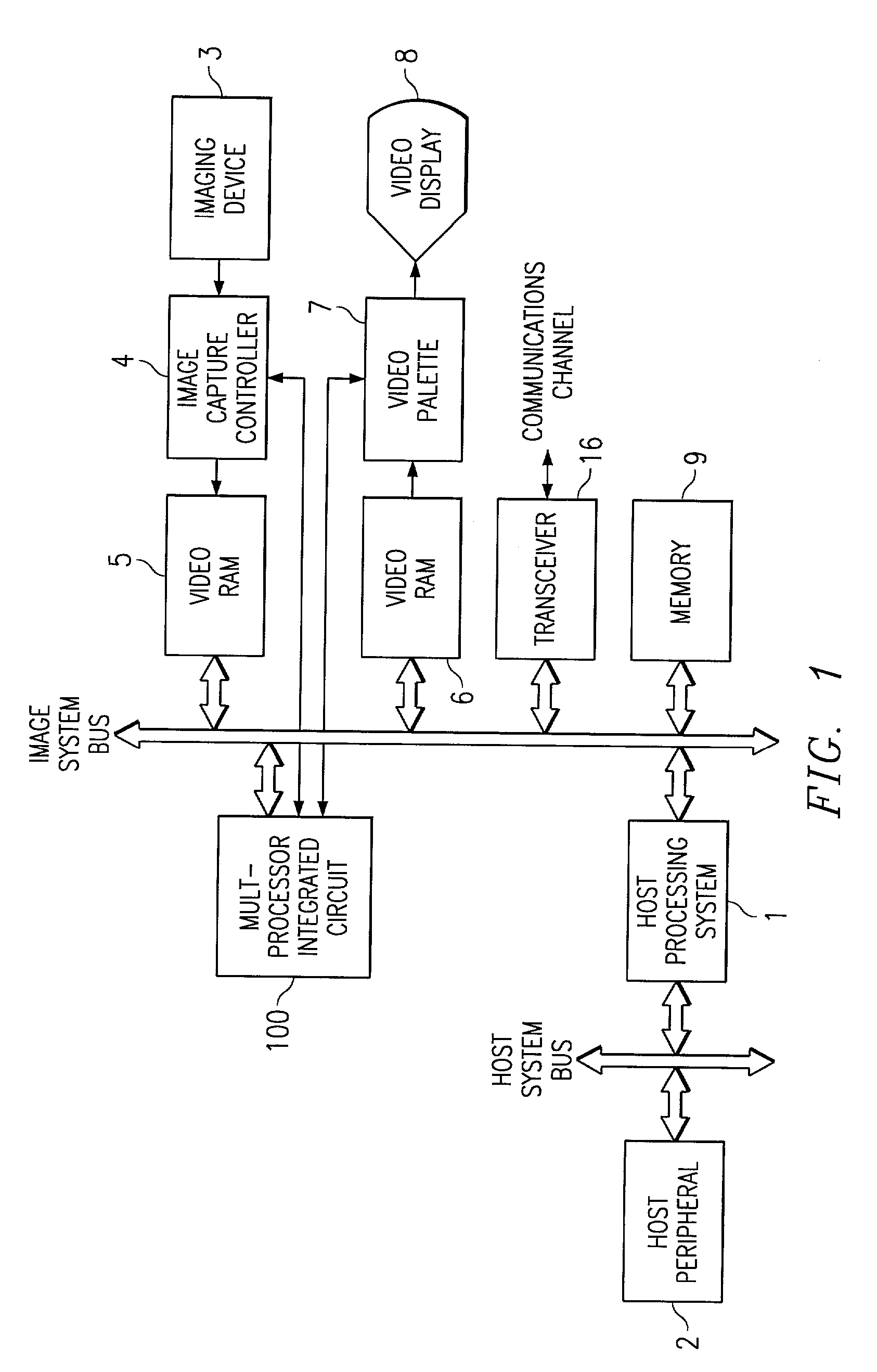
[0120]FIG. 1 is a block diagram of an image data processing system including a multiprocessor integrated circuit constructed for image and graphics processing according to this invention. This data processing system includes a host processing system 1. Host processing system 1 provides the data processing for the host system of data processing system of FIG. 1. Included in the host processing system 1 are a processor, at least one input device, a long term storage device, a read only memory, a random access memory and at least one host peripheral 2 coupled to a host system bus. Arrangement and operation of the host processing system are considered conventional. Because of its processing functions, the host processing system 1 controls the function of the image data processing system.

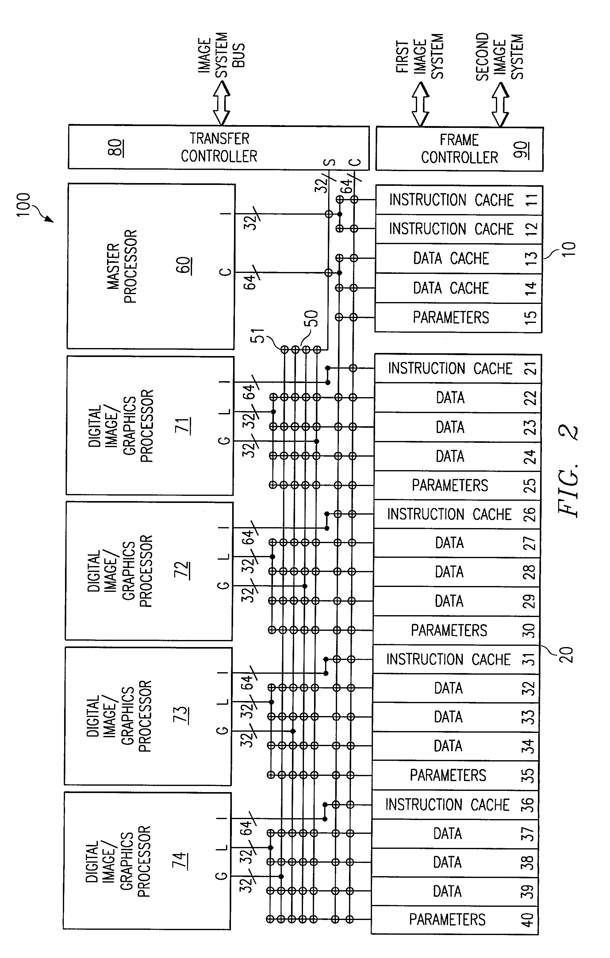
[0121]Multiprocessor integrated circuit 100 provides most of the data processing including data manipulation and computation for image operations of the image data processing system of FIG. 1. Multiproce...


PUM


Abstract

A data processing apparatus including a multiplier unit forming a product from L bits of each two data buses of N bits each N is greater than L. The multiplier forms a N bit output having a first portion which is the L most significant bits of the of product and a second portion which is M other bits not including the L least significant bits of the product, where N is the sum of M and L. In the preferred embodiment the M other bits are derived from other bits of the two input data busses, such as the M other bits of the first input data bus. An arithmetic logic unit performs parallel operations (addition, subtraction, Boolean functions) controlled by the same instructions. This arithmetic logic unit is divisible into a selected number of sections for performing identical operations on independent sections of its inputs. The multiplier unit may form dual products from separate parts of the input data. A single instruction controlling both the multiplier unit and the arithmetic logic unit permits addition of dual products. The dual products are temporarily stored in a data register permitting the multiply and add operations to be pipelined. The dual products are formed in one data word and added by a rotate / mask and add operation in a three input arithmetic unit.

Description

[0001]This application: is a divisional of U.S. patent application Ser. No. 09 / 678,746 filed Oct. 3, 2000 now U.S. Pat. No. 6,370,558; which is a divisional of U.S. patent application Ser. No. 08 / 632,785 filed Apr. 15, 1996 now U.S. Pat. No. 5,742,538; which is a divisional of U.S. patent application Ser. No. 08 / 160,297 filed Nov. 30, 1993, now U.S. Pat. No. 5,509,129.[0002]U.S. patent application Ser. No. 08 / 263,504 filed Jun. 21, 1994, now U.S. Pat. No. 5,471,592 issued Nov. 28, 1995 and entitled “MULTI-PROCESSOR WITH CROSSBAR LINK OF PROCESSORS AND MEMORIES AND METHOD OF OPERATION”; which is a continuation of U.S. patent application Ser. No. 08 / 135,754 filed Oct. 12, 1993, now abandoned; which is a continuation of U.S. patent application Ser. No. 07 / 933,865 filed Aug. 21, 1992, now abandoned; which is a continuation of U.S. patent application Ser. No. 07 / 435,591 filed Nov. 17, 1989 and now abandoned;[0003]U.S. Pat. No. 5,212,777, issued May 18, 1993, filed Nov. 17, 1989 and entit...

Claims


Application Information

Patent Timeline
Patent Type & Authority Patents(United States)
IPC IPC(8): G06F7/52G06F7/57G06F9/30G06F9/302G06F9/315G06F9/38
CPCG06F7/53G06F7/57G06F9/30014G06F9/30032G06F9/30036G06F9/30145G06F9/30167G06F9/3851G06F9/3853G06F9/3867G06F9/3885G06F2207/382
Inventor GUTTAG, KARL M.READ, CHRISTOPHER J.BALMER, KEITH
Owner TEXAS INSTR INC
Why Eureka
Try Eureka