Shrink-fit chuck with eccentric positioning

a chuck and eccentric positioning technology, applied in the field of chucking devices, can solve the problems of significant weight of these tools, slight tilting, and simplified use of tools, and achieve the effect of simple automatic use of tools

a chuck and eccentric positioning technology, applied in the field of chucking devices, can solve the problems of significant weight of these tools, slight tilting, and simplified use of tools, and achieve the effect of simple automatic use of tools

US7390153B2Inactive Publication Date: 2008-06-24GUHRING

Image

  • Shrink-fit chuck with eccentric positioning
  • Shrink-fit chuck with eccentric positioning
  • Shrink-fit chuck with eccentric positioning

Examples


Embodiment Construction

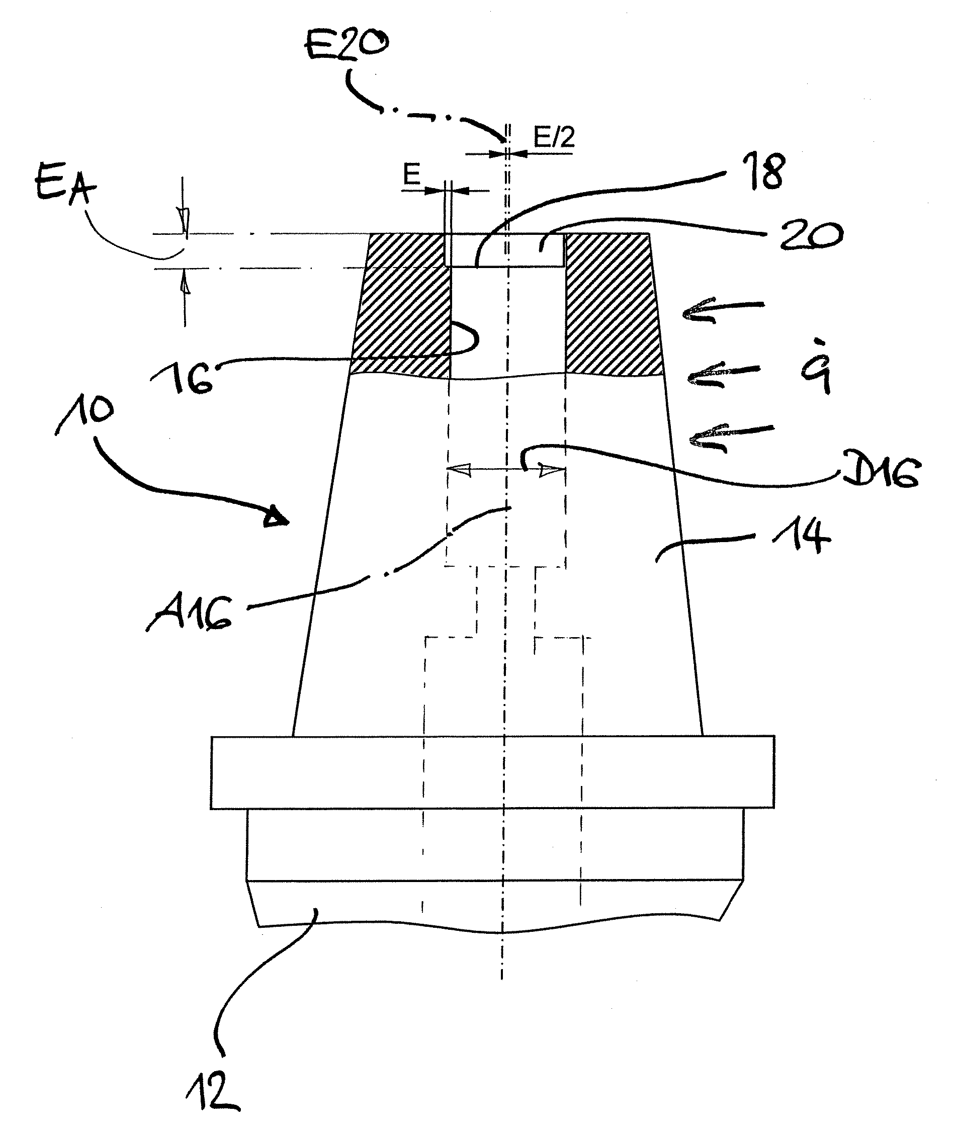
[0023]In FIG. 1, a shrink-fit chuck tool holder oriented vertically in a shrink fixture, which is not shown in detail, has been assigned reference numeral 10, which tool holder is intended for cylindrical tools, particularly circular cylindrical shank tools. The tool holder comprises a fastening shank 12, for example in the form of a hollow taper shank, which is not shown in detail and which is used to establish the connection to a machine tool. Reference numeral 14 designates a thermally expandable shrink section, comprising an inside recess 16 for the centered accommodation of a tool shank, which is not shown in detail, which recess is manufactured, preferably ground, to fit the outside diameter of the tool to be inserted. The inside recess 16 is formed by the circular cylindrical surface. The axis of the inside recess 16 has been assigned numeral A16.

[0024]The inside recess 16 has a diameter D16, which is adapted to the outside diameter of the tool such that shrink fit is guarant...


PUM

PropertyMeasurementUnit
Diameteraaaaaaaaaa
Displacementaaaaaaaaaa

Abstract

A shrink-fit chuck tool holder for cylindrical, particularly circular cylindrical, shank tools, including a fastening shank for establishing connection to a machine tool and a thermally expandable shrink section. The shrink section has an inside recess for accommodation of a tool shank and a pre-positioning section, which precedes the recess via a step and has an axial extension. The pre-positioning section is disposed eccentrically to the inside recess.

Description

BACKGROUND OF THE INVENTION[0001]1. Field of the Invention[0002]The present invention relates to a chucking device for fastening a tool in a machine tool, particularly in the form of a shrink-fit chuck tool holder for cylindrical, particularly circular cylindrical tools, and to a chucking device for tensioning tools by the shrink-fit chuck.[0003]2. Discussion of the Background[0004]In metal machining operations, today primarily machine tools with high levels of automation are used in production. The chucking and gripping systems, into which the insert tools are clamped and which in turn are held in corresponding holders of the machine tool, for example standardized cylinder shank holders or hollow taper shank (HSK) jaws, significantly influence the quality of workpieces as well as the efficiency of the production processes.[0005]Compared to conventional chucking devices, such as three-jaw chucks or extension chucks, shrink-fit chuck tool holders have greater rigidity in terms of the...

Claims


Application Information

Patent Timeline
24 Jun 2008
Publication
US7390153B2
IPC
B23C3/00
CPC
B23B31/1179; B23P11/027; B23B2265/12; Y10T409/30952; Y10T29/53704; Y10T279/17957; Y10T29/49865
Inventors
GRUBER, JOCHEN