Front mounted lifter for front load vehicle

a front load vehicle and lifter technology, applied in the direction of transportation items, refuse gathering, packaging goods types, etc., can solve the problems of operator injury, assorted breakdowns, leakage of connections, and requiring additional maintenance, and achieve the effect of convenient movemen

Inactive Publication Date: 2008-06-24
PERKIS MFG CO
View PDF218 Cites 52 Cited by
  • Summary
  • Abstract
  • Description
  • Claims
  • Application Information

AI Technical Summary

Benefits of technology

[0012]In accordance with another aspect of the invention, the lifter may be moved to stored position generally adjacent. to the front end of the vehicle when the vehicle is not being used for residential or small receptacle collection. When the vehicle is used on a residential or similar route, the lifter can be easily moved to a working position spaced forwardly of the vehicle and laterally of the collection container.

Problems solved by technology

As can appreciated, this is unduly time consuming, labor intensive, and can lead to operator injury due to the repeated lifting of the often heavy refuse receptacles.
While the use of the systems described above has resulted in savings of time and labor, the known systems still have several deficiencies.
Because hydraulic connections are typically required between the hydraulic system of the collection vehicle and the carrier-mounted lifter, these connections have been vulnerable to leakage and assorted breakdowns, requiring additional maintenance due, in part to the relatively large range of motion encountered by the container as it has moved over the cab to dump the contents thereof.
Additionally, some of the container-mounted lifters are compatible only with a specific style of residential refuse receptacle, and are unable to handle containers of different styles.
This can result in requiring several collection containers with different lifters for different collection routes, which results in added capital expense for additional equipment.

Method used


Image

  • Front mounted lifter for front load vehicle
  • Front mounted lifter for front load vehicle
  • Front mounted lifter for front load vehicle

Examples


Embodiment Construction

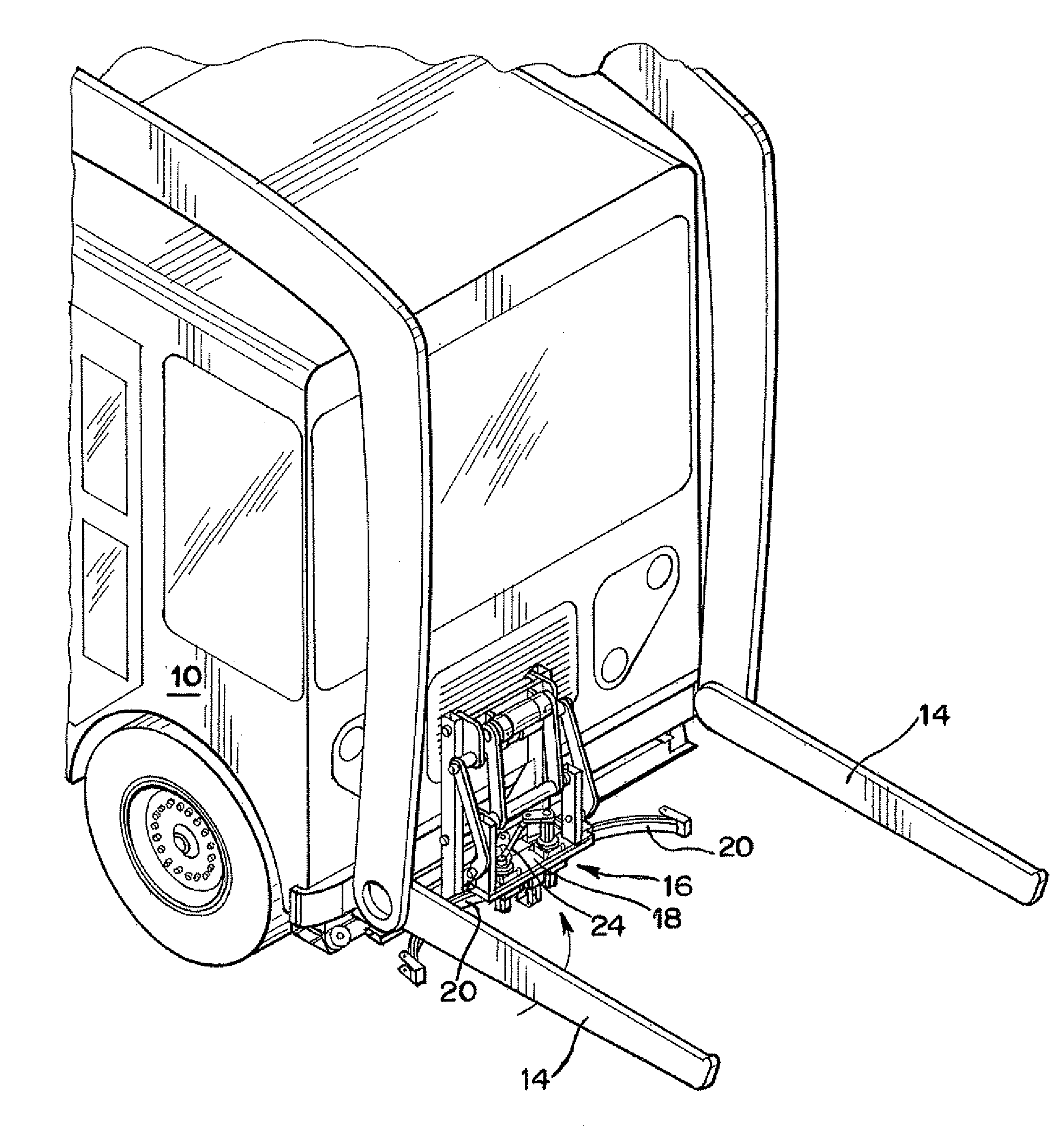
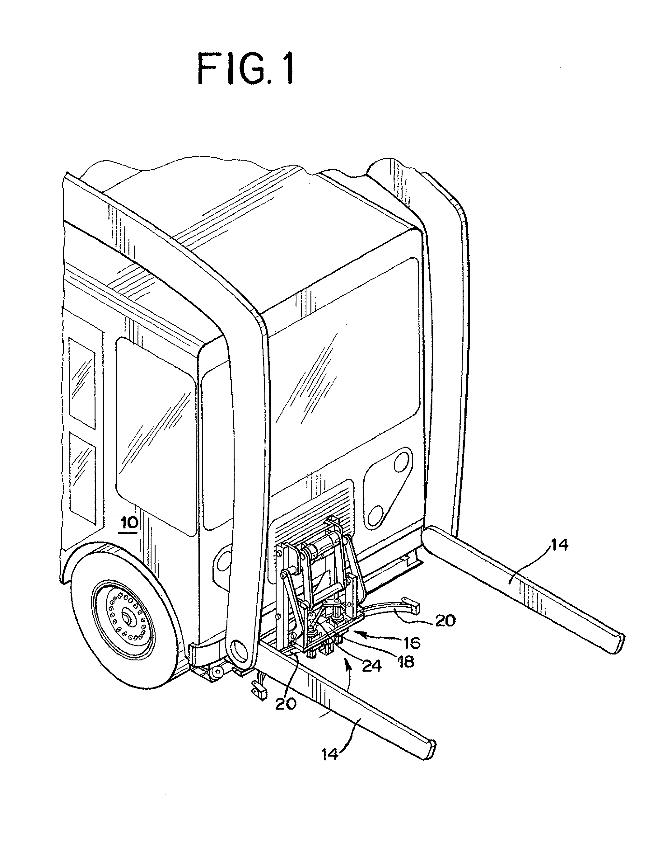
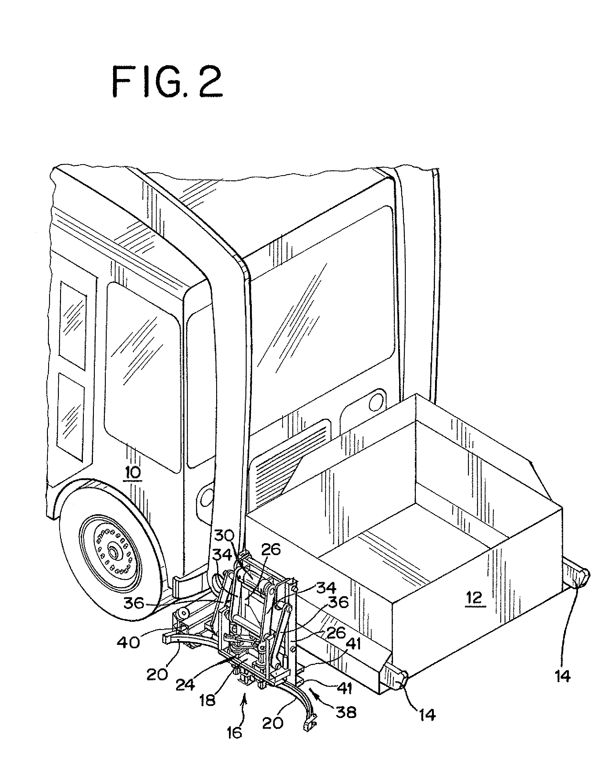
[0025]Turning to the figures of the drawings, there is seen in FIGS. 1-3 a front load refuse collection vehicle, generally designated 10, in combination with a collection container or box 12 (seen in FIGS. 2 and 3). The collection container 12 is carried on hydraulically-actuated forks 14 that move the collection container 12 from initial, refuse collection position, as shown in FIGS. 2 and 3, to an inverted position over a large refuse compartment (not shown) behind the cab of the vehicle 10 for dumping the contents thereof.

[0026]The refuse collection vehicle 10 is provided with a refuse receptacle lifter, generally designated 16, adapted to engage and invert a residential-style refuse receptacle (not shown) in order to dump its contents into the collection container 12.

[0027]The refuse receptacle lifter 16 is designed is accommodate a variety of residential roll-out refuse containers and includes a carriage 18 having a pair a pivotally-mounted lifter or grabber arms 20. The grabbe...


PUM


Abstract

A refuse receptacle lifter is disclosed that is mounted on a transporter secured to the front end of a collection vehicle rearwardly of an associated collection container. The transporter is adapted to move the lifter in a generally side-to-side direction relative to the collection container in order to move the lifter between a retracted position and a position in which it is spaced from the collection container so that it can engage a refuse receptacle. If the collection vehicle does not have a collection container. being carried on the front of the vehicle, the lifter may be moved to stored position generally adjacent to the front end of the vehicle.

Description

[0001]The present invention relates generally to a front load refuse collection vehicle and, more particularly, to an apparatus for, and methods of, refuse collection including a receptacle lifter assembly associated with. the front end of the refuse collection vehicle for lifting and dumping the contents of the receptacle into an intermediate refuse collection container located at the front end of the vehicle, which is lifted and dumped into collection vehicle when a sufficient amount of the refuse is collected.BACKGROUND OF THE INVENTION[0002]Front load refuse collection vehicles are in wide use in large-scale residential refuse collection. Typically, front load refuse collection vehicle have a front crew cab, a large refuse compartment behind the cab, and a pair of hydraulic-powered lift forks extending in front of. the truck which are adapted to be inserted into corresponding slots or sleeves associated with a relatively large refuse collection container. The forks are then able...

Claims


Application Information

Patent Timeline
Patent Type & Authority Patents(United States)
IPC IPC(8): B65F3/02B65F3/04
CPCB65F3/046B65F2003/023B65F2003/0273B65F2003/0276B65F2003/0279
Inventor RIMSA, JAMESARREZ, CARLOSARREZ, RAMIRO
Owner PERKIS MFG CO
Why Eureka
Try Eureka