Control device for automatic liquid handling system

a control device and liquid handling technology, applied in the direction of instruments, analytical methods using chemical indicators, laboratory glassware, etc., can solve the problems of inability to perform high-speed experiments, the number of experiments cannot be performed at high speed, and the inability to perform accurate and reliable experiments using microplates

Inactive Publication Date: 2008-06-24
HITACHI KOKI CO LTD
View PDF5 Cites 114 Cited by
  • Summary
  • Abstract
  • Description
  • Claims
  • Application Information

AI Technical Summary

Benefits of technology

[0009]In view of the foregoing, it is an object of the invention to provide a control device for an automatic liquid handling system capable of measuring a predetermined period of time starting from introduction of a reagent and introducing a reaction stop solution immediately after expiration of the predetermined period of time.
[0010]Another object of the invention is to provide a control device for an automatic liquid handling system having a self-diagnosing function that is capable of determining whether scheduled processes are executable or not during a time set in advance before execution of the processes and informing an operator of the results of determination.
[0011]Still another object of the invention is to provide a control device for an automatic liquid handling system capable of informing the operator of an accurate reaction time even if the system is temporarily stopped for some reasons.
[0012]In accordance with the invention, there is provided an automatic liquid handling system that includes a dispensing tip container, a reagent container, a microplate formed with a plurality of wells, and a dispensing head. The dispensing tip container has a plurality of holding portions for holding dispensing tips. The reagent container holds one or more reagents. The dispensing head has attachment portions to which at least one dispensing tip is attached. When one or more dispensing tips are attached to the attachment portions, the dispensing head is capable of performing sucking and expelling operations. Specifically, the dispensing head can suck the reagent into the dispensing tips from the reagent container, expel the reagent out from the dispensing tips, and drip the reagent into the wells of the microplate. Also, the dispensing head can suck the liquid in the specified wells of the microplate and drip the sucked liquid into another specified wells. Moving means is also provided for moving the dispensing head. The liquid handling system also includes a control device that controls the sucking and expelling operations performed by the dispensing head and also controls the moving means to control movements of the dispensing head. The control device has input means for inputting one or more processes to be executed by the dispensing head. Time measuring means is provided for measuring time starting from dripping the reagent into selected wells on the microplate by the expelling operation performed by the dispensing head.
[0013]According to another aspect of the invention, there is further provided self-diagnosing means for simulating time to execute the one or more processes to be executed by the dispensing head and determining whether the one or more processes are executable in the time set by time setting means. In this case, the time measuring means is not essential to the invention.

Problems solved by technology

In the development of new drugs, drug metabolic experiments are frequently carried out, and each experiment is involved with a large amount of work.
The above-described apparatus is disadvantageous in that with a single dispensing probe, a number of experiments cannot be performed at high speed.
However, accurate and reliable experiment cannot be performed with the automatic liquid handling system using the microplates.
Despite the fact that a small quantity of reagent shortens a reaction time, reaction time in different rows of the wells on the microplate varies due to variation in robot operation time, time needed for attaching and detaching the dispensing tips to and from the robot, and a work time needed for an operator to temporarily stop the robot to supplement the reagent.
The above-described disadvantages are particularly fatal in the case where a desired reaction time is short or a reagent reaction time expires during the robot is executing another process.
Further problem arises such that when the system is restarted due to occurrence of operational errors or accidental power down of the system, execution of the outstanding process may be finished before or after expiration of a desired reaction time.
In such cases, the results of experiment are not available and so the experiment per se is vain.

Method used


Image

  • Control device for automatic liquid handling system
  • Control device for automatic liquid handling system
  • Control device for automatic liquid handling system

Examples


Embodiment Construction

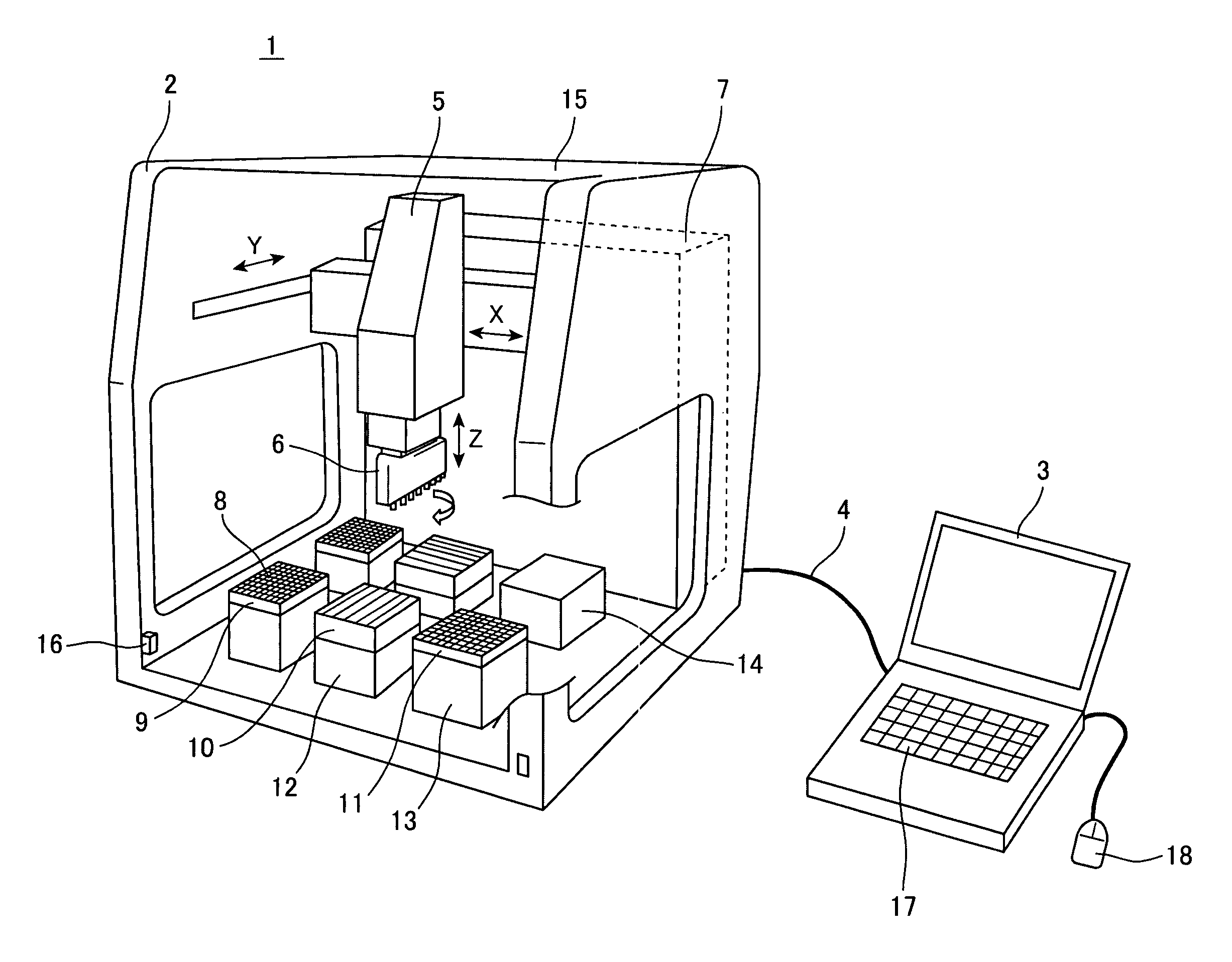
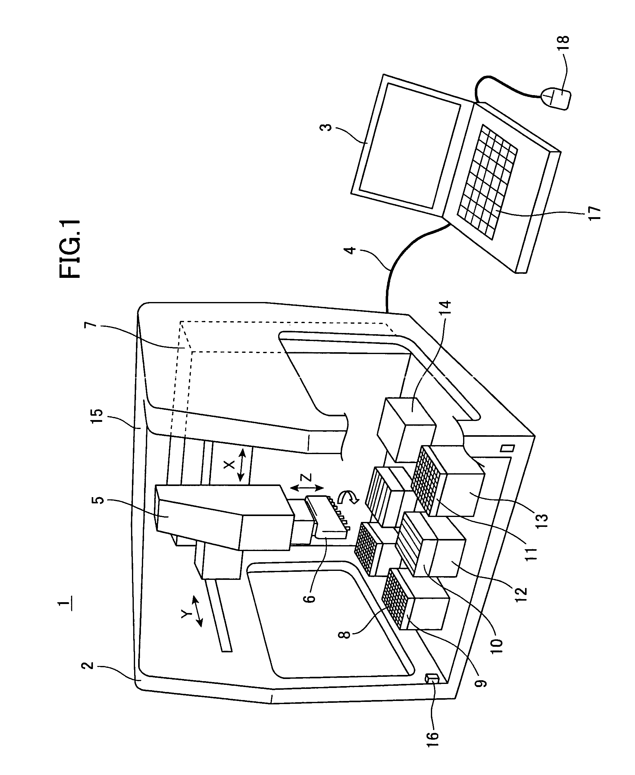
[0021]A preferred embodiment of the present invention will be described with reference to the drawings. FIG. 1 shows an automatic liquid handling system 1 according to a preferred embodiment of the present invention. The automatic liquid handling system 1 includes a main body 2 and a control device 3 connected together with a communication cable 4 such as a LAN (Local Area Network) cable. A general-purpose personal computer is used as the control device 3. The main body 2 of the automatic liquid handling system 1 includes a robot 5 capable of moving and stopping in 3D space, a dispensing head 6 provided at a tip end of the robot 5, and a driving circuit 7 for driving the main body 2 based upon conditions input into the control device 3.

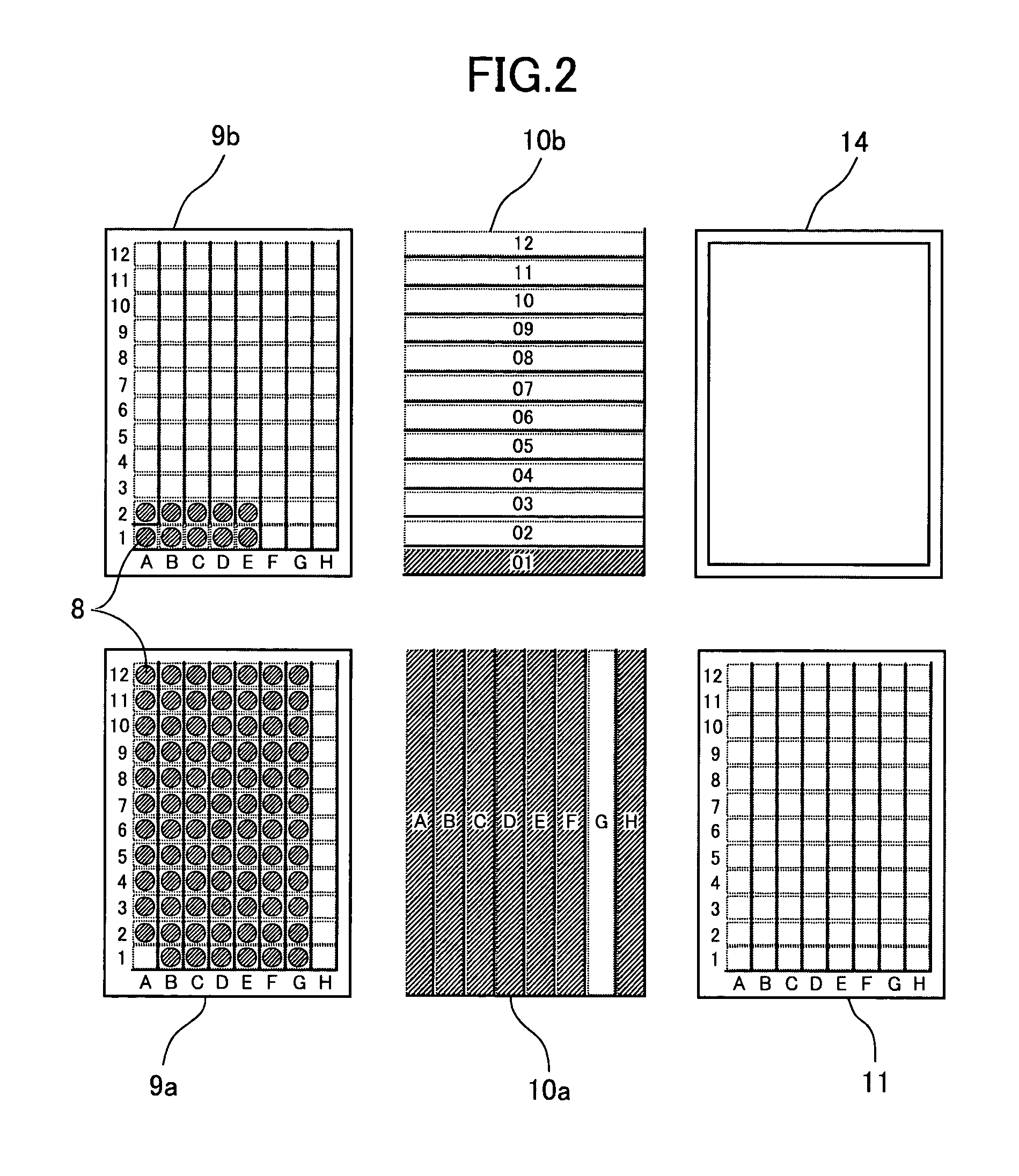
[0022]The robot 5 has three orthogonal axes, X, Y, and Z, and is capable of being moved by stepper motors (not shown) to a predetermined position. Servo-motors can be used instead of the stepper motors. A plurality of dispensing tips 8 aligned at an e...


PUM

PropertyMeasurementUnit
diameteraaaaaaaaaa
diameteraaaaaaaaaa
timeaaaaaaaaaa

Abstract

In reagent reaction experiments using microplates, a desired period of time can be set for determining the time to introduce a reaction stop solution after introduction of a reagent. The set time is measured starting from the introduction of the reagent and the reaction stop solution is introduced immediately after expiration of the set time. A control device for an automatic liquid handling system having the above-described reaction time managing feature is also provided with a self-diagnosing function that is capable of determining whether scheduled processes are executable or not during the time set before execution of the processes and informing an operator of the results of determination.

Description

BACKGROUND OF THE INVENTION[0001]1. Field of the Invention[0002]The present invention relates to the control device for an automatic liquid handling system that manages reaction time of reagent or enzymes that are used in drug metabolic experiments.[0003]2. Description of Related Art[0004]In the development of new drugs, drug metabolic experiments are frequently carried out, and each experiment is involved with a large amount of work. It is therefore essential to reduce mistakes caused by human error. To this end, human operations tend to be replaced by automatic mechanical operations.[0005]It is important to manage a reagent reaction time in drug metabolic experiments. Japanese Patent Application Publication No. 2000-83650 discloses an automatic test apparatus used in conducting metabolic experiments. The apparatus includes a three-dimensionally movable robot having a tip end on which a single dispensing probe is mounted. With this apparatus, a solution of specimen is dripped into ...

Claims


Application Information

Patent Timeline
Patent Type & Authority Patents(United States)
IPC IPC(8): G01N21/00G01N35/10C12M1/34G01N35/00
CPCG01N35/0092Y10T436/2575
Inventor OSAWA, HIDETAKATOI, HIROATSUYAMADA, KENJIOHKAWARA, TADASHI
Owner HITACHI KOKI CO LTD
Why Eureka
Try Eureka