Magnetic resonance imaging apparatus, coil system for a magnetic resonance imaging apparatus and magnetic resonance imaging method

a magnetic resonance imaging and coil system technology, applied in the direction of magnetic measurement, instruments, measurement devices, etc., can solve the problems of difficult to uniformly difficult to avoid deterioration of the reception signal, and difficult to optimize the distance between the transmitter and the receiver. , to achieve the effect of improving the signal-noise ratio and optimizing the distan

Active Publication Date: 2008-06-24
TOSHIBA MEDICAL SYST CORP
View PDF8 Cites 32 Cited by
  • Summary
  • Abstract
  • Description
  • Claims
  • Application Information

AI Technical Summary

Benefits of technology

[0013]The present invention has been made in light of the conventional situations, and it is an object of the present invention to provide a magnetic resonance imaging apparatus, a coil system for a magnetic resonance imaging apparatus and a magnetic resonance imaging method which make it possible to optimize a distance between a transmitter for radio transmission connected with element coils in a receiver coil and a receiver, which makes a pair to the transmitter, of a signal processing system to improve deterioration of signal-noise ratio due to attenuation of signals involving spatial propagation of reception signals transmitted by radio.
[0017]The magnetic resonance imaging apparatus, the coil system for a magnetic resonance imaging apparatus and the magnetic resonance imaging method as described above make it possible to optimize a distance between a transmitter for radio transmission connected with element coils in a receiver coil and a receiver, which makes a pair to the transmitter, of a signal processing system to improve deterioration of signal-noise ratio due to signal attenuation involving spatial propagation of reception signals transmitted by radio.

Problems solved by technology

However, the increase in the number of element coils in the reception coil increases cable wiring for transmitting reception signals obtained in the element coils to a signal processing system, and wiring of cables connected to moving element coils are subjected to various restrictions.
Therefore, the distance between a transmitter for wireless communications connected to each of the element coils and the receiver in the signal processing system varies depending on the position of the element coil, so that it is difficult to uniformly optimize the distance between the transmitter and the receiver.
However, this approach cannot avoid deterioration in a reception signal caused by signal compression with respect to a dynamic range required for an MRI apparatus and a complicated circuit structure.
Moreover, known wireless coil systems have no means for keeping a uniform spatial distance between the transmitter connected to each of the reception element coils whose arrangement varies with each imaging section, as described above, and the receiver in the signal processing system.
In addition, the variations in the SNR lead to image quality degradation.

Method used


Image

  • Magnetic resonance imaging apparatus, coil system for a magnetic resonance imaging apparatus and magnetic resonance imaging method
  • Magnetic resonance imaging apparatus, coil system for a magnetic resonance imaging apparatus and magnetic resonance imaging method
  • Magnetic resonance imaging apparatus, coil system for a magnetic resonance imaging apparatus and magnetic resonance imaging method

Examples


first embodiment

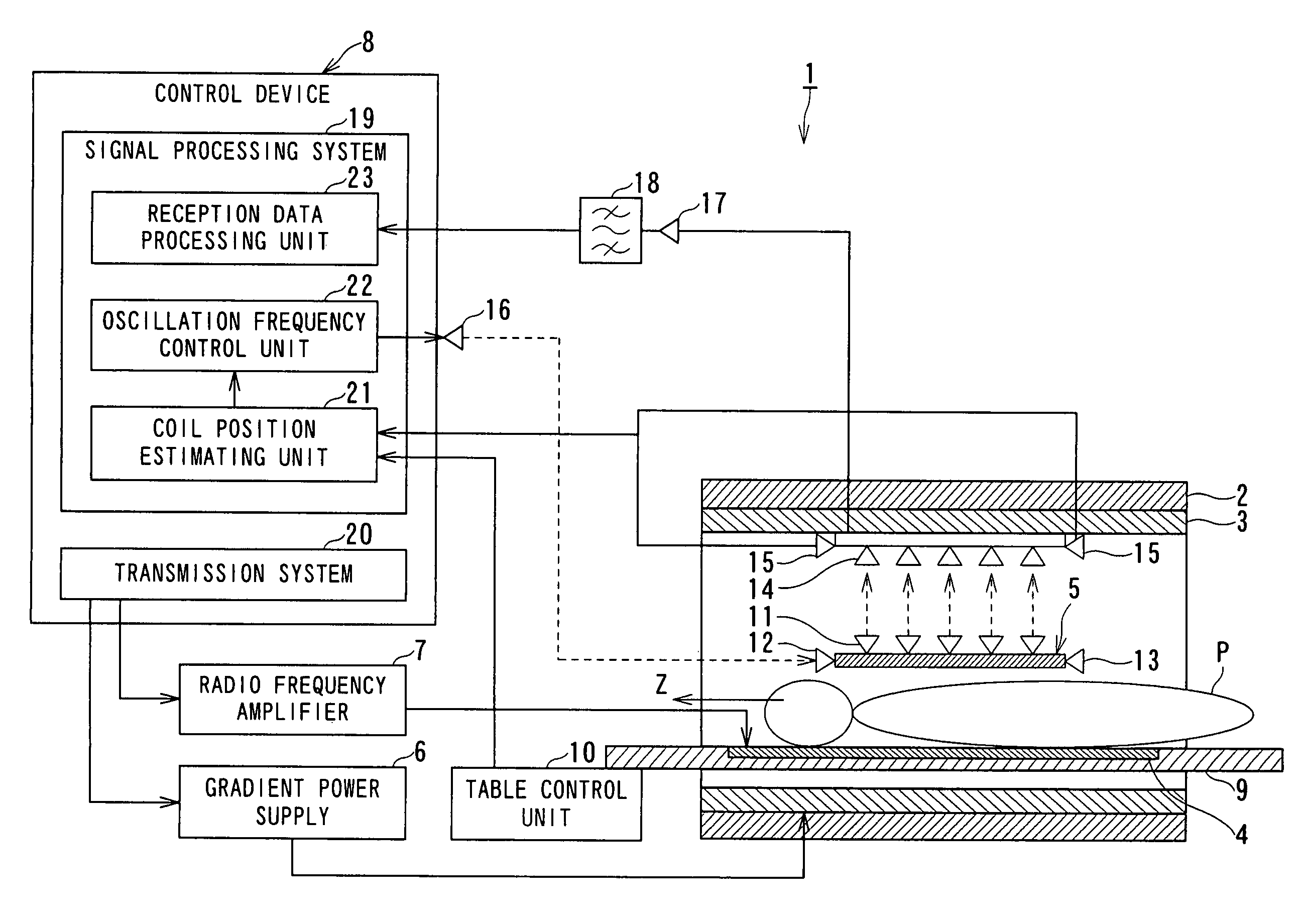
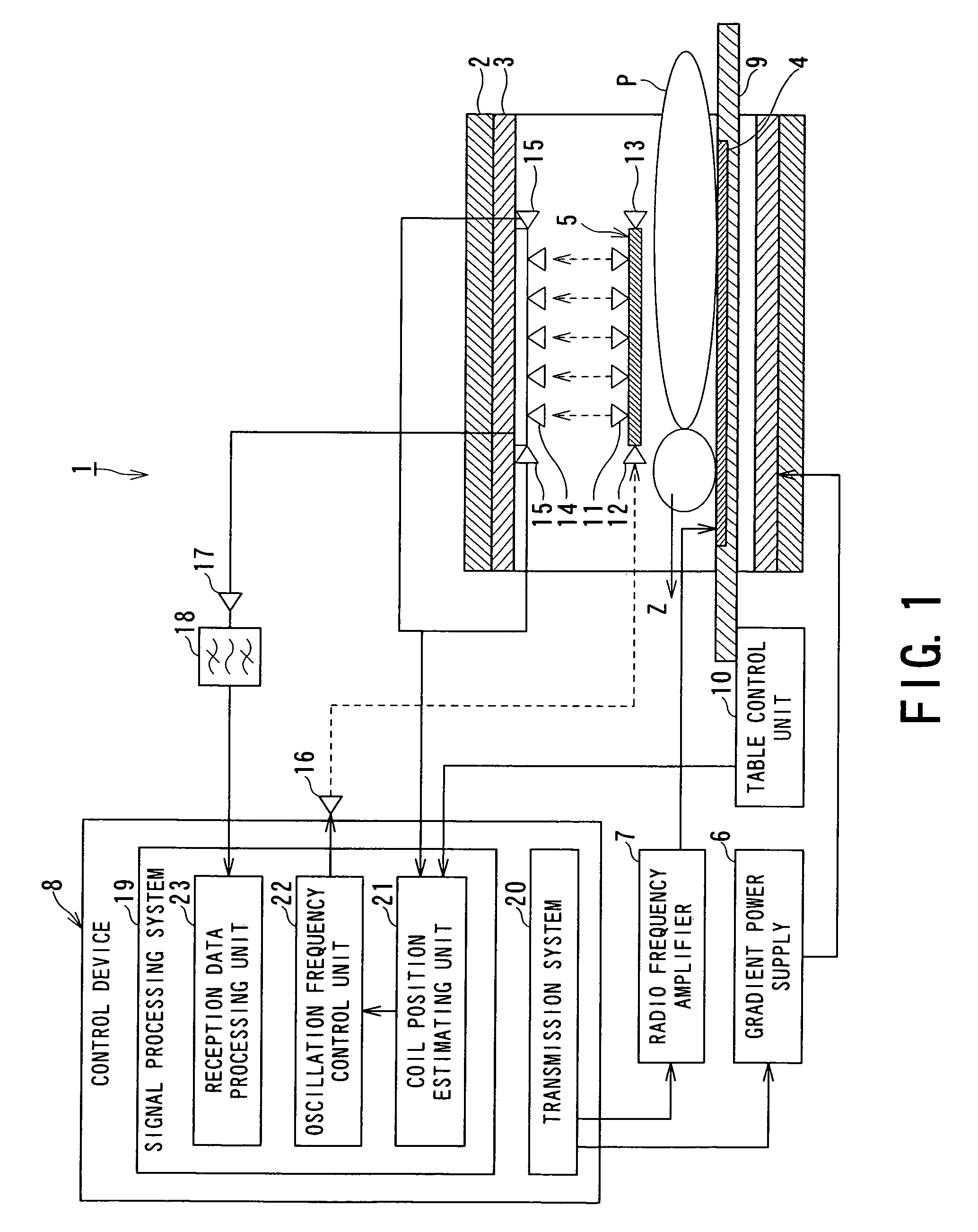
[0028]FIG. 1 is a diagram of a magnetic resonance imaging apparatus according to the present invention.

[0029]A magnetic resonance imaging apparatus 1 includes a static field magnet 2, a gradient coil 3, a radio-frequency transmission coil 4, a radio-frequency reception coil 5, a gradient power supply 6, a radio frequency amplifier 7, and a control device 8 as main elements. The static field magnet 2, the gradient coil 3, the radio-frequency transmission coil 4, and the radio-frequency reception coil 5 are disposed on a gantry (not shown). The cylindrical gradient coil 3 is disposed inside the cylindrical static field magnet 2 forming a static field. Inside the gradient coil 3, an imaging region is present, and the radio-frequency transmission coil 4, the radio-frequency reception coil 5, and a table 9 are disposed. An object P is placed on the table 9.

[0030]The table 9 is provided with a table control unit 10. The table 9 can be moved in the body axis direction (Z-direction) of the ...

second embodiment

[0080]FIG. 7 is a diagram of a magnetic resonance imaging apparatus according to the present invention.

[0081]A magnetic resonance imaging apparatus 1A illustrated in FIG. 7 is different from the magnetic resonance imaging apparatus 1 illustrated in FIG. 1 in that a radio-frequency reception coil 5 is provided with a single reception-signal transmission antenna 11, in that a control device 8 has a different functional structure, and in that the frequency filter 18 is replaced with a circuit selection unit 50. Other structures and operations are substantially the same as in the magnetic resonance imaging apparatus 1 illustrated in FIG. 1. Therefore, the same reference numerals are used for similar components as in FIG. 1, and the description thereof is omitted.

[0082]In the magnetic resonance imaging apparatus 1A, the radio-frequency reception coil 5 is provided with the single reception-signal transmission antenna 11. Each of a plurality of reception-signal reception antennas 14 dispo...


PUM


Abstract

A magnetic resonance imaging apparatus includes a receiver coil, at least one transmitter antenna, receiver antennas, a signal selection unit and a processing unit. The receiver coil receives a nuclear magnetic resonance signal from an object as a reception signal. The transmitter antenna transmits the reception signal by radio. The receiver antennas are arranged to receive the reception signal. The signal selection unit selects a reception signal received by a specific receiver antenna. The processing unit reconstructs an image of the object from the reception signal selected by the signal selection unit.

Description

BACKGROUND OF THE INVENTION[0001]1. Field of the Invention[0002]The present invention relates to a magnetic resonance imaging apparatus, a coil system for a magnetic resonance imaging apparatus and a magnetic resonance imaging method which excite nuclear spin of an object magnetically with a RF (radio frequency) signal having a Larmor frequency and reconstruct an image based on a magnetic resonance signal generated due to the excitation, and more particularly, to a magnetic resonance imaging apparatus, a coil system for a magnetic resonance imaging apparatus and a magnetic resonance imaging method which transmit a reception signal received by a RF receiver coil to a signal processing system by radio.[0003]2. Description of the Related Art[0004]MRI (Magnetic Resonance Imaging) apparatuses are used as monitoring devices in medical field conventionally.[0005]An MRI apparatus is an apparatus which generates gradient magnetic fields in X, Y and Z axis directions by gradient coils on an i...

Claims


Application Information

Patent Timeline
Patent Type & Authority Patents(United States)
IPC IPC(8): G01V3/00
CPCG01R33/34G01R33/341G01R33/3692
Inventor ADACHI, KOHEI
Owner TOSHIBA MEDICAL SYST CORP
Why Eureka
Try Eureka