Vapor compression refrigerating device
a refrigerating device and vapor compression technology, applied in the direction of engine starters, machines/engines, lighting and heating apparatus, etc., can solve the problem of taking a certain time to reach the
- Summary
- Abstract
- Description
- Claims
- Application Information
AI Technical Summary
Benefits of technology
Problems solved by technology
Method used
Image
Examples
first embodiment
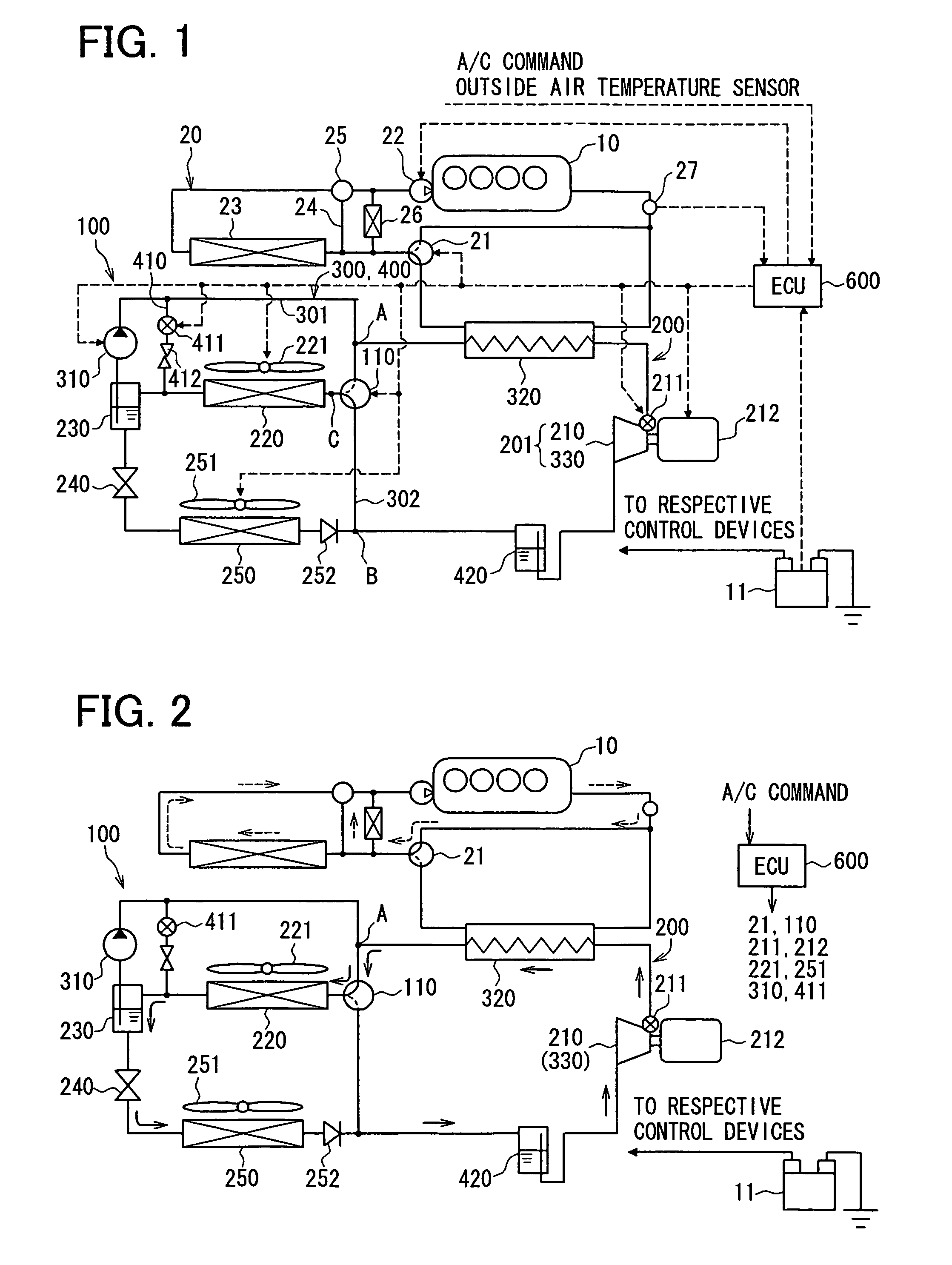
[0036]FIG. 1 shows a schematic system structure of a vapor compression refrigerating device 100 according to a first embodiment of the present invention, wherein the refrigerating device 100 is applied to an air conditioning system for a hybrid vehicle having a water cool type engine 10 and a motor for running, which are driving power sources for the vehicle.
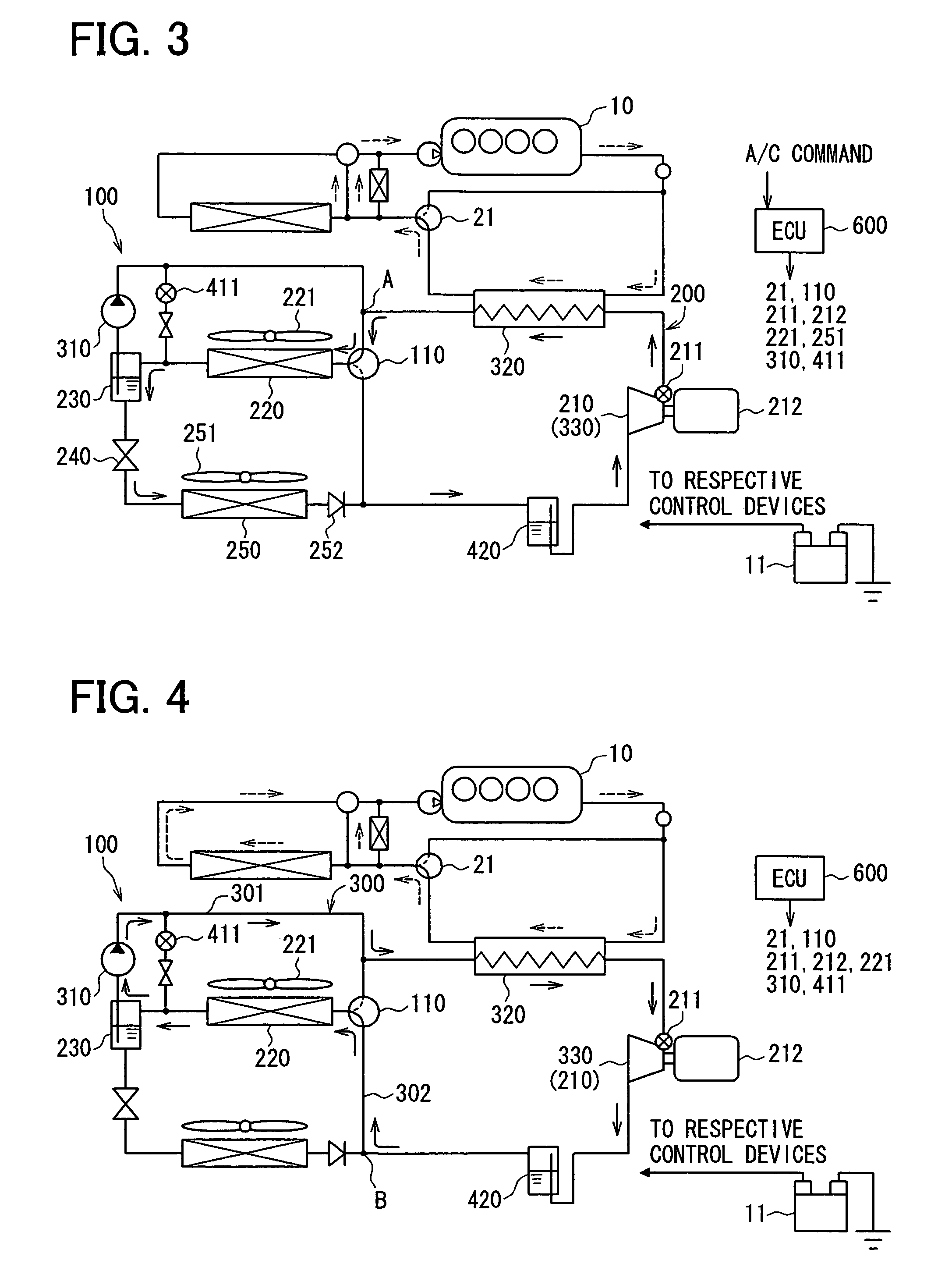
[0037]As shown in FIG. 1, a Rankine cycle 300 and a heat pump cycle 400 as well as a well known refrigerating cycle 200 are incorporated in the vapor compression refrigerating device 100 (hereafter, simply referred to as the refrigerating device 100).
[0038]The refrigerating cycle 200 utilizes low temperature heat and high temperature heat by transferring heat from a low temperature side to a high temperature side, and includes a compressor device 210, a condenser device 220, a gas-liquid separator 230, a depressurizing device 240, and an evaporator 250, which are connected circularly in this order.
[0039]The compressor device 210...
second embodiment
[0087]A second embodiment of the present invention is described with reference to FIGS. 10 to 12. The second embodiment is different from the first embodiment in that the heat pump cycle 400 is replaced with a hot gas cycle 500. More specifically, the liquid pump bypass passage 410, the ON-OFF valve 411 and the orifice 412 of the first embodiment are removed, and the hot gas cycle 500 is instead formed by commonly using the compressor device 210 and heating device 320 and by newly adding a switching passage 510.
[0088]The switching passage 510 is provided between a juncture D and a juncture E, wherein the juncture D is an intermediate point between the liquid pump 310 and the heating device 320 and the juncture E is an intermediate point between the switching valve 110 and the check valve 252. An ON / OFF valve 511 for opening and closing the switching passage 510 and an orifice 512 with a fixed opening degree are provided in the switching passage 510. The ON / OFF valve 511 is controlle...
PUM
 Abstract
Description
Claims
Application Information
 - R&D
- Intellectual Property
- Life Sciences
- Materials
- Tech Scout
- Unparalleled Data Quality
- Higher Quality Content
- 60% Fewer Hallucinations
Browse by: Latest US Patents, China's latest patents, Technical Efficacy Thesaurus, Application Domain, Technology Topic, Popular Technical Reports.
© 2025 PatSnap. All rights reserved.Legal|Privacy policy|Modern Slavery Act Transparency Statement|Sitemap|About US| Contact US: help@patsnap.com


