Cooling system of an engine for the inside of a generator

a technology of cooling system and engine, which is applied in the direction of machines/engines, combustion air/fuel air treatment, mechanical equipment, etc., can solve the problems of not ensuring timely cooling of the portions with a mass of heat in the engine, and achieve the effect of high cooling efficiency of the engine, simple and compact structure, and increased jointing surfaces of the cooling system

Inactive Publication Date: 2008-07-01
WUXI KIPOR POWER CO LTD
View PDF3 Cites 32 Cited by
  • Summary
  • Abstract
  • Description
  • Claims
  • Application Information

AI Technical Summary

Benefits of technology

[0004]The object of the present invention is to solve the technical problem as the above-mentioned, so as to provide a cooling system for an engine inside the power generator, which has a compact, simply, rational structure; and the connecting surfaces thereof is more with the requirements for cooling becoming reasonable; which also can ensure to timely cool the portions with a mass of heat in the engine and provide a high cooling effect.
[0008]This present invention has a simple, compact and rational structure. By using the cool air suction hood and cool air guides plate to partially enclose the engine, the power generator, the exhaust pipe and the muffler, the cool air taken in by the cooling fan continuously cool the above-mentioned members, which then is exhausted outside the chambers through the exhaust channel. Thus, according to the present invention, the jointing surfaces of the cooling system are increased. The requirements for cooling the engine are more reasonable so that the portions (such as the circumference around the cylinder of the engine, the exhaust pipe, the oil shell at the bottom of the engine) in the engine with a mass of heat are ensured to be timely cooled and provide a highly cooling effective for the engine.

Problems solved by technology

Such kind of the cooling structure has less connecting surfaces so that the cooling and ventilating chamber so constructed easily meets the sealing requirements, but can not ensure the timely cooling for the portions with a mass of heat in the engine (such as the circumference around the cylinder of the engine, the exhaust pipe and oil shell at the bottom of the engine).

Method used


Image

  • Cooling system of an engine for the inside of a generator
  • Cooling system of an engine for the inside of a generator
  • Cooling system of an engine for the inside of a generator

Examples


Embodiment Construction

[0012]The features and advantages of the present invention will be clearly understood with reference to the following detailed description and the demonstration of the attached drawings of a preferred embodiment.

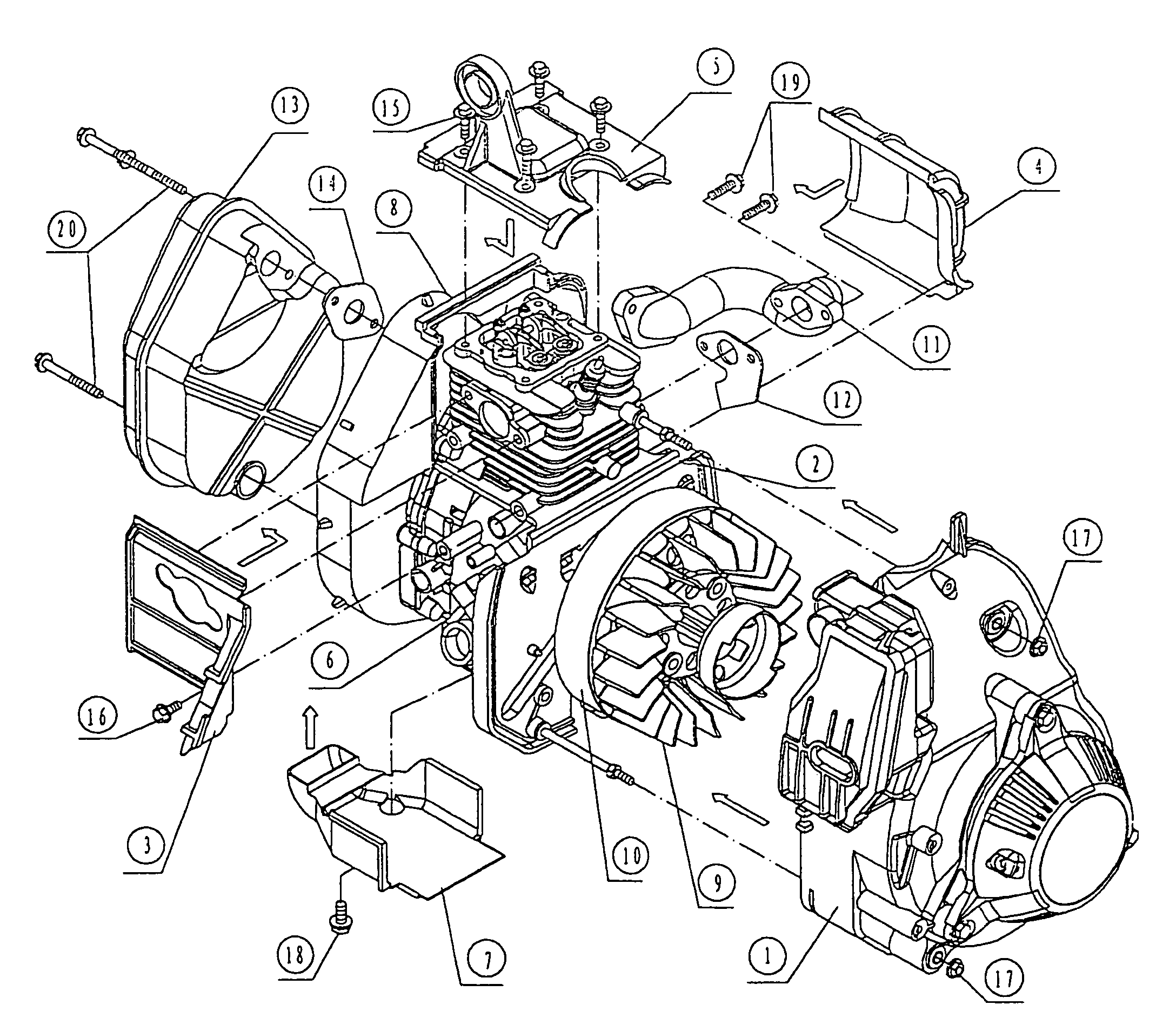
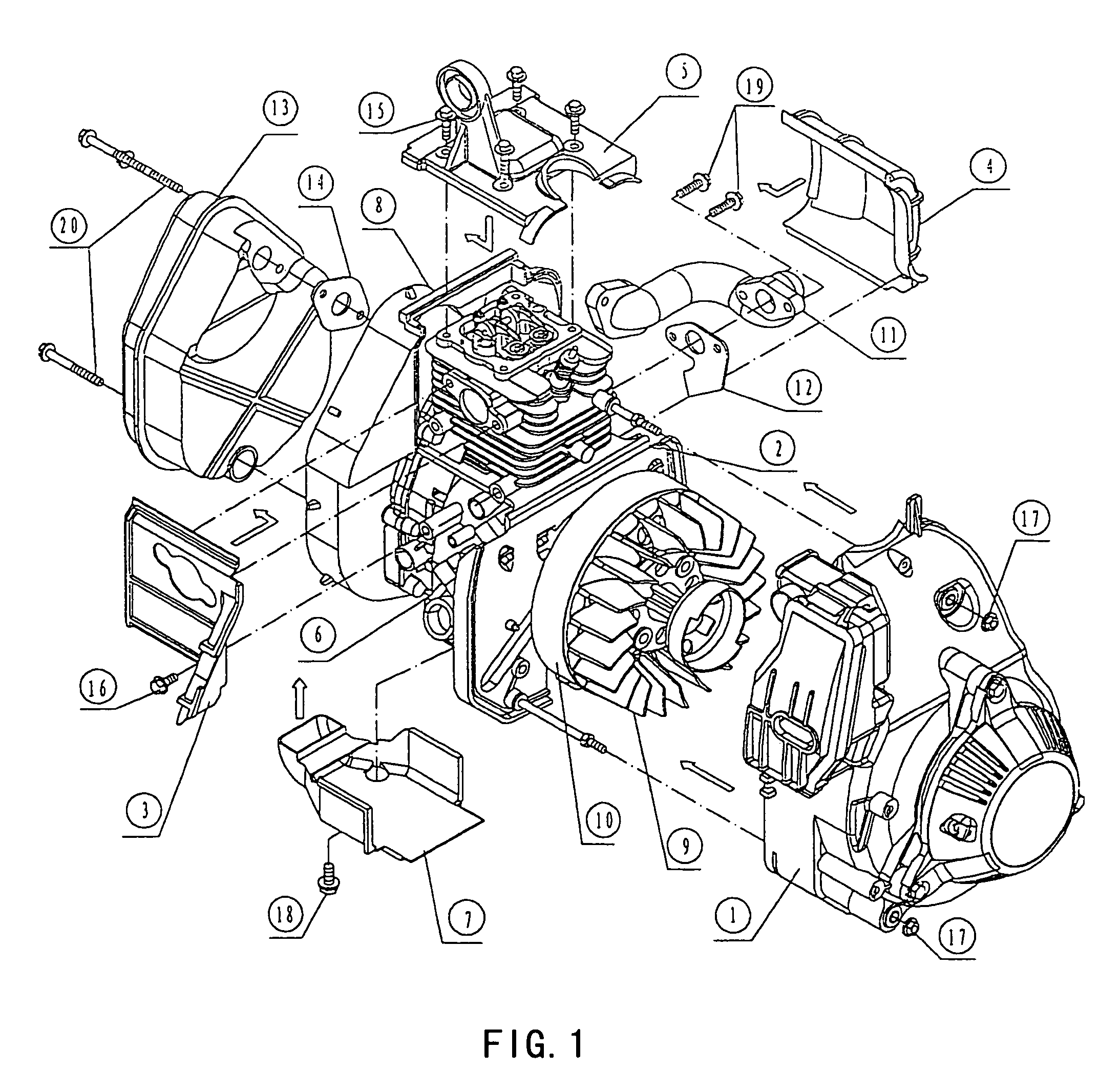
[0013]A cool air suction hood 1 according to the present invention is made by the process of polyester injection molding or aluminum-alloy die casting, and is connected to the side cover 2 of the engine housing with bolts 17. The left air guide plate 3 and the right air guide plate 4 on the upper of the engine are made by the process of polyester injection molding or steel sheet pressing, and are secured on the side surface of the engine housing 6 with bolts 16. The left air guide plate 3 and the right air guide plate 4 on the upper of the engine, the lifting lugs made by the process of aluminum-alloy die casting or steel sheet pressing, the engine cylinder hood 5 secured with the bolts 15 on the cylinder head of the engine and the engine housing 6 provided with engaging sur...


PUM


Abstract

The present invention relates to a cooling system for an engine inside a power generator, in the field of the power generator, which mainly includes a cool air suction hood, an engine housing side cover, an engine housing, a cool air cooling fan, an exhaust pipe; the cool air suction hood is jointed to the engine housing side cover, the left air guide plate and the right air guide plate on the upper of the engine secured to the engine housing, thus form two main cooling and ventilating chambers A and B on the left and right upper portion of the engine. An engine bottom air guide plate is secured to the bottom of engine housing side cover and forms the bottom cooling and ventilating chamber C of the engine with the side cover and an engine crank case rear cover. The engine crank case rear cover, the above-mentioned members, a heat insulation chamber body, a sealing ring and a heat insulation chamber rear hood form a double chamber cooling means of the secondary cooling cycle chamber D. The jointing surfaces of the cooling system are increased. The requirements for cooling the engine are more reasonable so that the portions of the engine with high heat are ensured to be timely cooled and provide a highly cooling effective for the engine.

Description

FIELD OF THE TECHNOLOGY[0001]The present invention relates to a power generator, more particularly, to a cooling system for an engine inside a power generator.DESCRIPTION OF THE RELATED ART[0002]An enforced air-cooled engine requires adequate cool air for cooling the portions around the cylinders of the engine and the oil shell at the bottom of the engine. Because these two portions generate a mass of heat and are at so high temperature, so that the heat must be timely diffused to ensure that the engine keeps normal running and has a longer working life.[0003]In the art, the cooling system for an engine inside the power generator generally has a fully enclosed cooling and ventilating chamber, i.e. the cooling hood and the guide hood of the cooling and ventilation chamber enclose the engine, the power generator, exhaust pipe and mufflers. The cool air taken in by the cooling fan cools all of the surfaces of the above-mentioned members and is exhausted out of the cooling and ventilati...

Claims


Application Information

Patent Timeline
Patent Type & Authority Patents(United States)
IPC IPC(8): F01P1/02F02B77/04F01P1/00F01P1/06F02B63/04
CPCF01P1/02F02B63/04F01P1/06F02B63/042F01P2001/005
Inventor XIAO, HENGLIN
Owner WUXI KIPOR POWER CO LTD
Why Eureka
Try Eureka