Power assisted vehicle

a technology of power assisted vehicles and power sources, applied in the direction of electric propulsion mounting, electric devices, sport apparatus, etc., can solve the problems of high precision requirements, high noise, and power consumption, and achieve the effects of reducing power consumption, improving transmission efficiency, and reducing power consumption

Inactive Publication Date: 2008-07-01
CHIU PO LIN +2
View PDF9 Cites 20 Cited by
  • Summary
  • Abstract
  • Description
  • Claims
  • Application Information

AI Technical Summary

Benefits of technology

[0006]Accordingly, it is an objective of the present invention to provide a power assisted vehicle that is capable of self-propelled going forward, reduces the consumption on powers provided by batteries, and improves transmission efficiency.
[0007]The power assisted vehicle comprises a frame body, a pushing handlebar pivoted to the frame body, a wheel portion and an auxiliary propelling device. The auxiliary propelling device includes an auxiliary wheel and at least one transmission portion disposed in the auxiliary wheel. When two friction wheels of the transmission portion fasten to two sides of a friction ring of the auxiliary wheel and the two power sources is in reverse to drive the two friction wheels for rotating, a wheel rim and a tire are then driven to produce rotations. The power assisted vehicle is therefore capable of self-propelled going forward only push it at a specific speed by user. A processing device is further installed in the power assisted vehicle. The auxiliary propelling device is then activated when the power assisted vehicle is at a specific speed. The energy consumption for the power source is reduced and increased transporting efficiently and regulated the power sources distribution for powering the power assisted vehicle. The usage of the power assisted vehicle is more efficient.

Problems solved by technology

The regulation may consume electricity and torsions generated by motors may be easily affected by the available capacity remaining in batteries.
For any type of transmission mechanism, the precision requirement is really high and the noise is quite loud.

Method used


Image

  • Power assisted vehicle
  • Power assisted vehicle
  • Power assisted vehicle

Examples


Embodiment Construction

[0018]Wherever possible, the same reference numbers are used in the drawings and the description to refer to the same or like parts.

[0019]Referring to the related figures for the power assisted vehicle according to a preferred embodiment of the present invention, wherein the same elements are described by the same reference numerals.

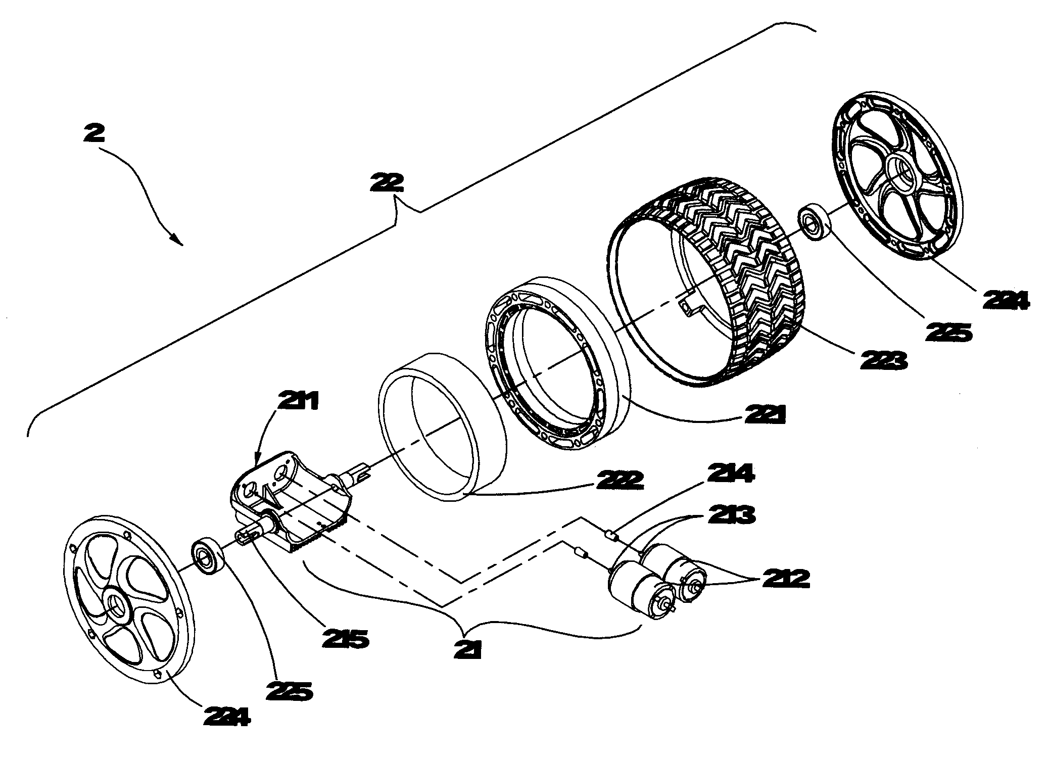
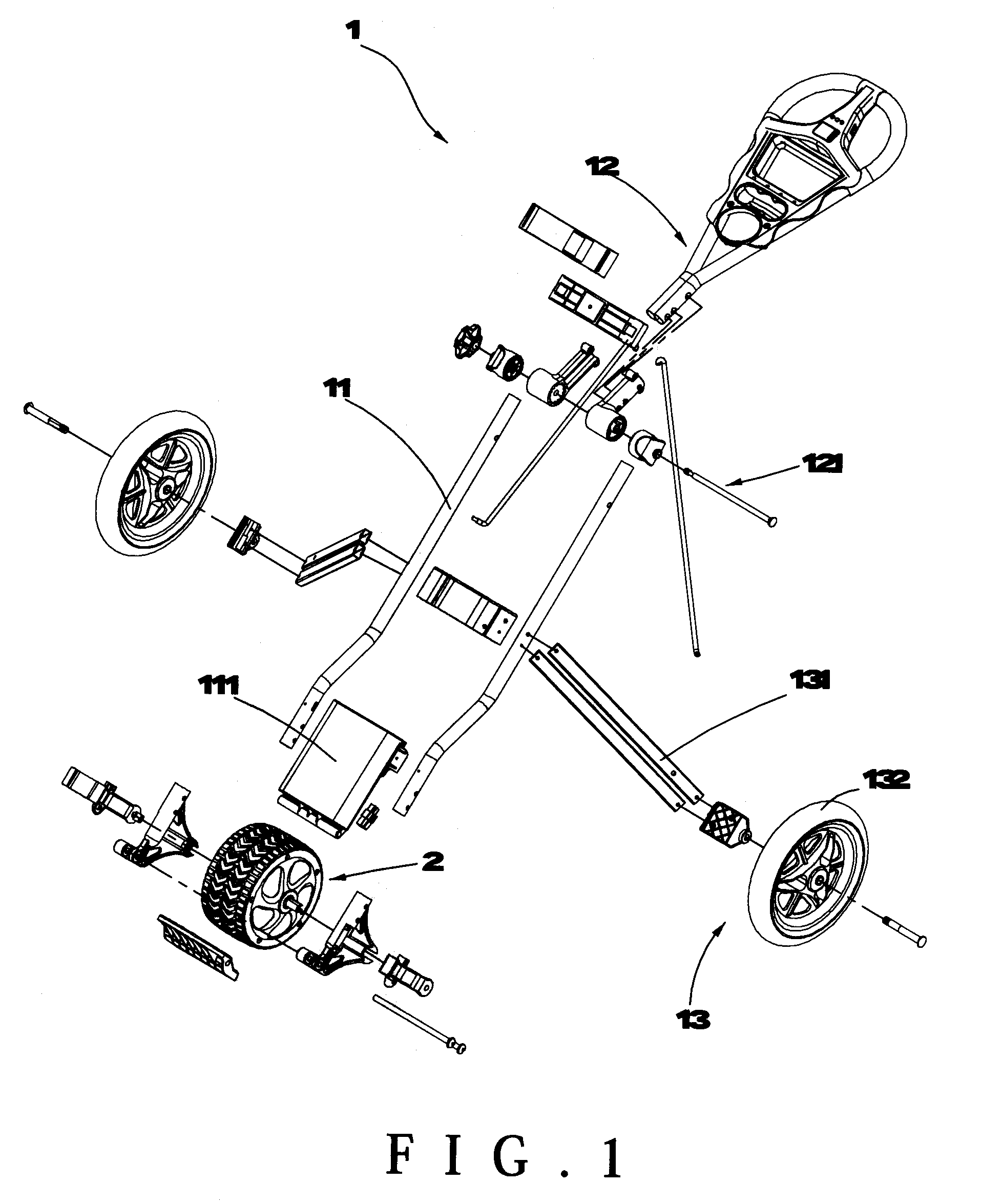
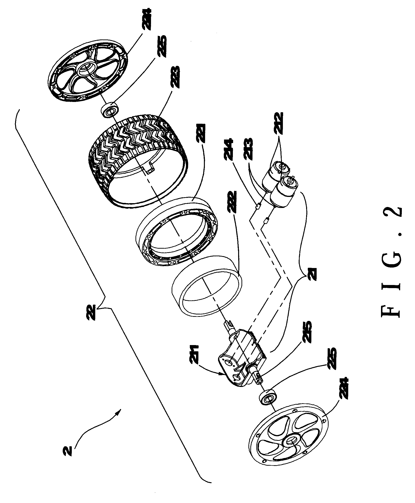
[0020]Referring to FIG. 1, an exploded assembly drawing of a power assisted vehicle according to a preferred embodiment of the present invention. The power assisted vehicle 1 comprises a frame body 11, a pushing handlebar 12 pivoted to the frame body 11, a wheel portion 13 disposed on the frame body 11 and an auxiliary propelling device 2. An external power 111 (e.g. a battery) is disposed on the frame body 11. The external power 111 can be easily replaced to keep power supplied by the external power 111. In addition, a pivot point between the pushing handlebar 12 and the frame body 11 having a positioning member 121 (e.g. screws screwed to nuts as shown...


PUM


Abstract

A power assisted vehicle includes an auxiliary propelling device disposed to the frame body. The auxiliary propelling device has an auxiliary wheel and at least one transmission portion disposed in the auxiliary wheel. When two friction wheels of the transmission portion fasten to two sides of a friction ring of the auxiliary wheel, and the two power sources is in reverse to drive the two friction wheels for rotating, a wheel rim and a tire are further driven to produce rotations. The power assisted vehicle is therefore capable of self-propelled going forward without any external force. A processing device is further disposed in the power assisted vehicle. The auxiliary propelling device is then activated when the power assisted vehicle is at a specific speed. The energy consumption for the power sources is then reduced and the service life is extended. The transmission force distribution generated from the power sources is further adjustable. The usage of the power assisted vehicle is more efficient.

Description

BACKGROUND OF THE INVENTION[0001]1. Field of the Invention[0002]The present invention generally relates to a vehicle design, more particular to this vehicle is equipped with an auxiliary propelling device and an electric motor for powering the power assisted vehicle.[0003]2. Description of the Related Art[0004]Conventional electric vehicles and light transportations usually rely on electric motors to transmit powers. For designing traditional motors, external gears, belts are utilized to drive tires for rotating. However, the speeds for those transportations are to regulate voltages to achieve. The regulation may consume electricity and torsions generated by motors may be easily affected by the available capacity remaining in batteries. For any type of transmission mechanism, the precision requirement is really high and the noise is quite loud. The transmission mechanism may also have larger volume and weight.[0005]To overcome the foregoing shortcomings, the inventor of the present ...

Claims


Application Information

Patent Timeline
Patent Type & Authority Patents(United States)
IPC IPC(8): B60K1/02
CPCB60K1/04B62B1/02B62B5/0026B60K7/0007B62B5/067B60K17/043B60K2007/003B60K2007/0046B60K2007/0061B60L2200/30B60L2220/44B60L2220/46B62B1/002B62B5/004B62B5/0053B62B5/0066B62B5/0069A63B55/61
Inventor CHIU, PO-LINTSAY, SHERN-JICHANG, CHING-PIAO
Owner CHIU PO LIN
Why Eureka
Try Eureka