Bladder actuator for a railroad retarder

a technology for retarders and actuators, which is applied in the direction of mechanical devices, track-braking member co-operation, transportation and packaging, etc., can solve the problems of accelerated bushing wear, dirty environment of rail marshalling yards, and ruggedness and non-stop,

Inactive Publication Date: 2008-07-01
PRECISION RAIL & MFG
View PDF33 Cites 13 Cited by
  • Summary
  • Abstract
  • Description
  • Claims
  • Application Information

AI Technical Summary

Benefits of technology

[0009]The present invention pertains to a low-maintenance bladder actuator for a low-profile railroad retarder. The actuator has an internal guide mechanism and internal limit stops. The guide mechanism has a concentric, telescoping guide rod and guide sleeve that are removably bolted to upper and lower plates. An integral cast head forms the upper plate and a stop sleeve that absorbs the cyclical 20,000 pound loads of the actuator. This enables the guide rod to remain concentricly aligned. The guide mechanism has sufficient stroke length (SL) and includes a long internal bushing with a low wear rate. The stop sleeve engages the lower plate to form the lower limit stop. The stop sleeve includes an inwardly extending flange that engages an outwardly extending flange of the guide sleeve to form an upper limit stop. The stop sleeve and guide sleeve form a cam lock connection for easy assembly.
[0010]One advantage of the present actuator is its internal guide and limit stops require minimal maintenance. The stop sleeve is provided to form the upper and lower limit stops. The guide rod does not form these stops. The 20,000 pound impact loads produced by the actuator do not pass through guide rod or the four (4) bolts that secure it to the upper plate of the caste head. These bolts remain tight and maintain the guide rod in its centrally aligned position. In addition, the outside diameter (OD) of the guide rod and guide sleeve are closely matched to the inside diameter (ID) of the central opening of the upper and lower plates. The ID of the central opening of the upper and lower plates are within about three-thousandths of an inch of the OD of the shaft of the guide rod or guide sleeve, respectively. Much of the cyclical 1,000 pound lateral loads experienced by the guide rod and guide sleeve pass directly to the sidewall of the opening of the plates. The bolts remain tight and keep the guide rod and guide sleeve in their intended alignment. This increases the life of the internal friction bearings, and results in a less frequent maintenance schedule to ensure proper bolt integrity, guide rod and guide sleeve alignment and bearing life. Thus, the present invention reduces maintenance and financially costly and serious life threatening accidents that can result from equipment malfunctions, each of which is a major concern of the railroad industry.
[0011]Another advantage of the present actuator is its stop sleeve and guide sleeve design. The cast head integrally joins the stop sleeve and upper plate. No bolts are needed to secure the stop sleeve to the upper plate. The 20,000 pound impact loads experienced by the stop sleeve do not affect its alignment. The stop sleeve is longer than the guide sleeve, so it forms the lower stop by engaging the lower plate. The concentric alignment of the guide sleeve is maintained by the relatively large diameter of its middle securement flange, which allows eight (8) bolts to secure it to the lower plate. The large number of bolts and their radial distance from the centerline of the actuator minimize the affect of any slight loosening of the bolts, which keeps maintenance and down time to a minimum.
[0012]A further advantage of the present actuator is that its guide mechanism and limit stops accommodate stroke length (SL) and friction bearing length. The actuator has a stroke length of about 3⅜ inches. The guide sleeve bushing has a length of about 3½ inches. The ID of the bushing is within about five thousandths of an inch of the OD of the shaft of the guide rod. Significant attention is given to the length of the bushing and the tight tolerances between the ID of the bushing and OD of the guide rod to achieve a tight sliding fit between them. The relatively long bushing spreads the 1,000 pound lateral load over a long length and large surface area to reduce the frictional forces and reduce the rate of wear of the bushing surface that engages the guide rod, particularly at the ends of the bushing. The length of the bushing also helps maintain the guide rod in its intended central alignment. The longer the bushing, the smaller the permissible shift in guide rod alignment due to the well known principle of rise (tolerance) over run (bushing length).
[0013]A still further advantage of the present actuator is the cam lock connection between the guide sleeve and stop sleeve. The cam lock connection facilitates assembly and eliminates the need for some welds during assembly.

Problems solved by technology

The railroad marshalling yard environment is dirty, rugged and non-stop.
A problem with an internal guiding mechanism for a bladder actuator is the rapid wear of the internal friction bearing.
Accelerated wear of the bushing occurs when the lateral loads push guide rod out of concentric alignment.
Deflection of the guide rod causes an exponential increase in the lateral load, which increases the frictional forces and wear on the bushing.
The worn bushing allows further misalignment of the guide rod, increased lateral loads, and even more rapid wear of the busing.
This is a particularly significant problem with actuators for low profile retarders because a short bushing length is not able to distribute the lateral load over a large busing surface area.
The ends of the bushing tend to wear quickly.
Yet, frequent maintenance to replace the bushing is time consuming and expensive and results in costly down-time for the yard.
Another problem occurs when an internal guide rod forms the upper and lower stops of the actuator as in U.S. Pat. No. 6,220,400.
Even a slight loosening of the guide rod can result in some lateral movement, which will exponentially increase the loads on and wear rate of the internal bushing or bearing.
This loosening of the guide rod, or even the potential loosening of the guide rod, significantly increases the need for routine maintenance and possible down time.
A further problem with an internal guide mechanism for bladder actuator for a low-profile railroad retarder is the trade off between stroke length (SL) and bushing length.
Inadvertent contact with the wheels can result in derailments and loss of life.
Yet, a short bushing will have difficulty maintaining concentric alignment of the guide rod and will wear quickly and require frequent maintenance.

Method used


Image

  • Bladder actuator for a railroad retarder
  • Bladder actuator for a railroad retarder
  • Bladder actuator for a railroad retarder

Examples


Embodiment Construction

[0023]While this invention is susceptible of embodiment in many different forms, the drawings show and the specification describes in detail a preferred embodiment of the invention. It should be understood that the drawings and specification are to be considered an exemplification of the principles of the invention. They are not intended to limit the broad aspects of the invention to the embodiment illustrated.

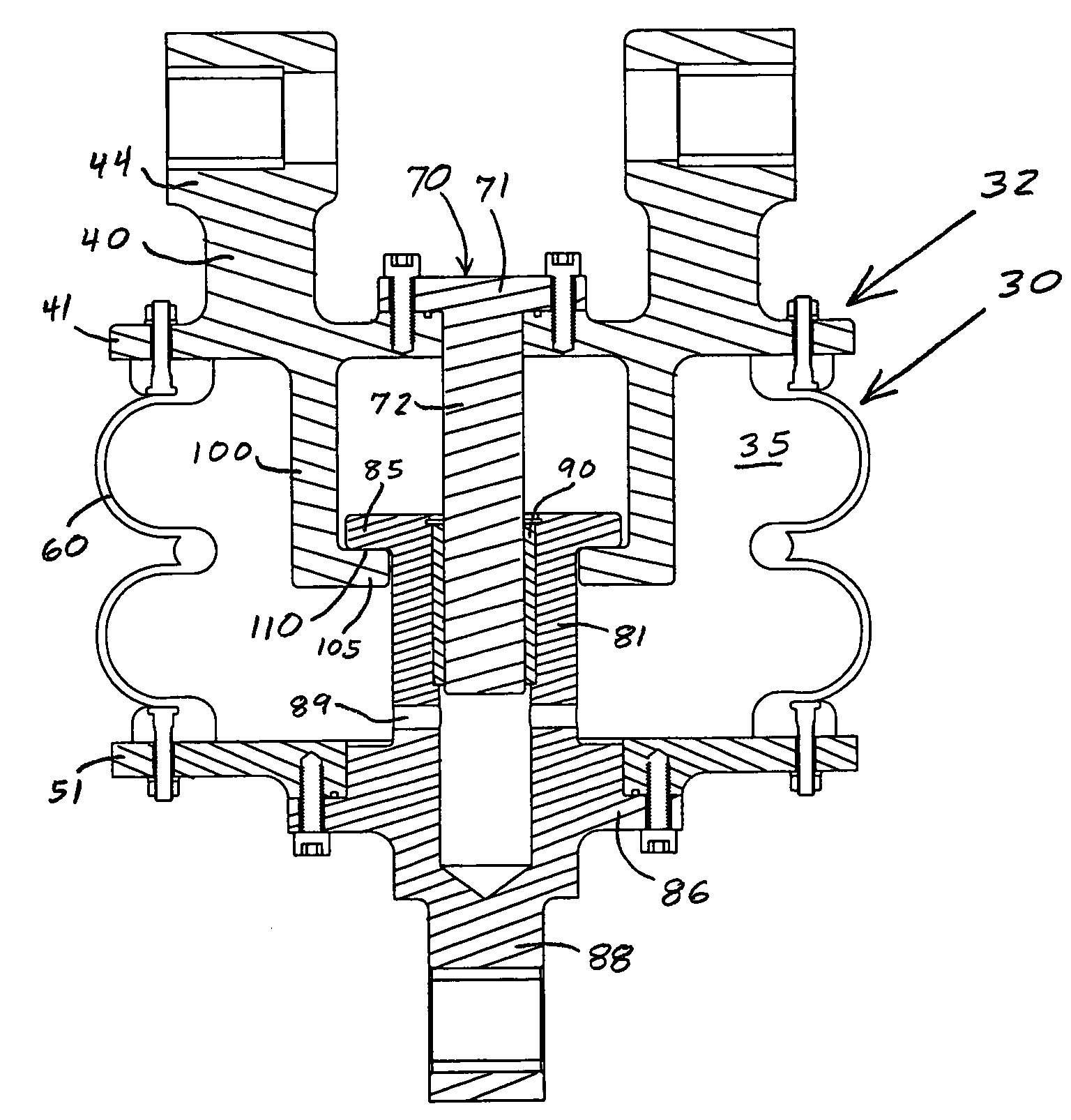
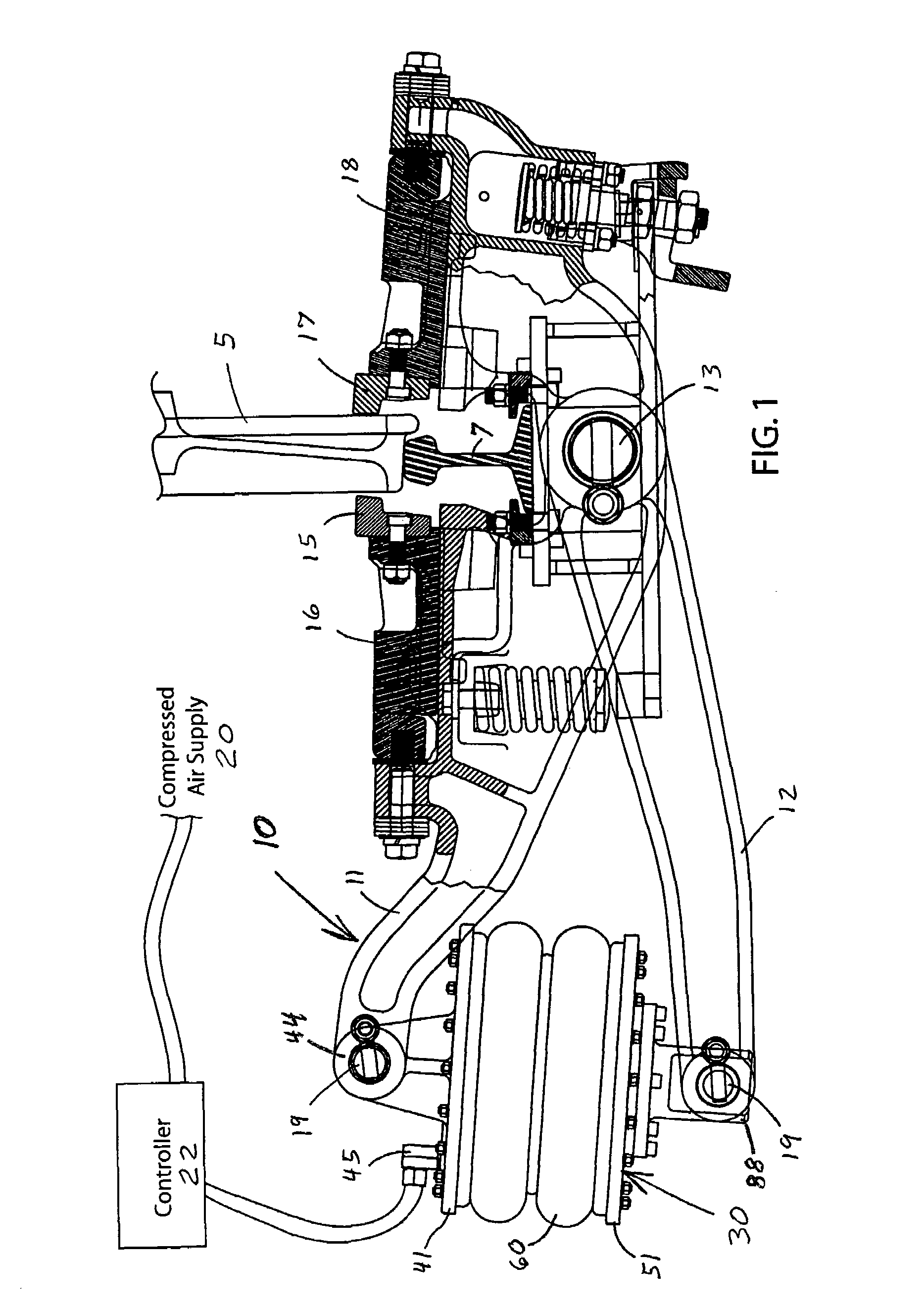
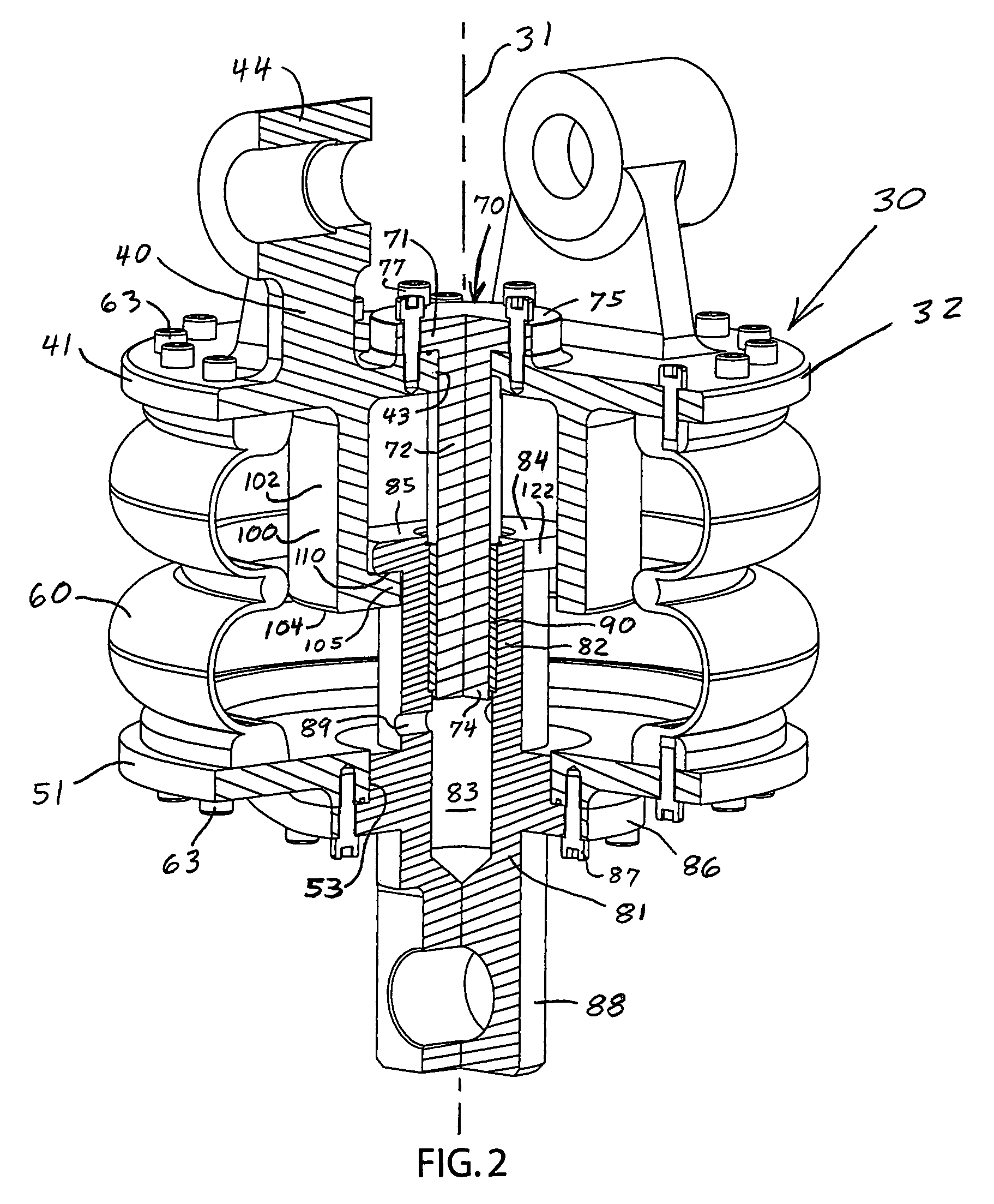
[0024]FIG. 1 shows a wheel 5 of a railroad car riding on one rail 7 of a track. The wheel 5 is passing by a low profile retarder 10 having upper and lower levers 11 and 12 pivotally joined by a pin 13 that acts as a fulcrum. The upper lever 11 has a brake pad 15 and lateral positioning mechanism 16 on the field side of the rail 7. The lower lever 12 has a brake pad 17 and lateral positioning mechanism 18 on the gauge side of the rail 7. The fulcrum pin 13 is located directly under the rail 7. The free end of each lever 11 and 12 has a circular opening for receiving a tubular p...


PUM


Abstract

The present invention pertains to a low-maintenance bladder actuator for a low-profile railroad retarder. The actuator has an internal guide mechanism and internal limit stops. The guide mechanism has a concentric, telescoping guide rod and guide sleeve that are removably bolted to upper and lower plates. An integral cast head forms the upper plate and a stop sleeve that absorbs the cyclical 20,000 pound loads of the actuator. This enables the guide rod to remain concentricly aligned. The guide mechanism has sufficient stroke length (SL) and includes a long internal bushing with a low wear rate. The stop sleeve engages the lower plate to form the lower limit stop. The stop sleeve includes an inwardly extending flange that engages an outwardly extending flange of the guide sleeve to form an upper limit stop. The stop sleeve and guide sleeve form a cam lock connection for easy assembly.

Description

BACKGROUND OF THE INVENTION[0001]Bladders or bellows are well known commercial devices for controlling the relative movement between two parts. These devices typically include a guide and upper and lower limit stops. U.S. Pat. No. 1,169,250 to Fulton discloses a shock absorber for water pipes. The device has a collapsible and expandable vessel located between and secured to centrally perforated inflexible end walls. The apparatus includes a guide for limiting relative lateral motion of the plates. U.S. Pat. No. 1,928,368 to Coffey pertains to vehicle jack with three telescoping cylindrical sections. A collapsible and extendable rubber sack or lining is used inside the telescoping sections. Shoulders and flanges limit outward telescoping movement. U.S. Pat. No. 3,935,795 to Hawley discloses a bellows actuator with opposed ends that are closed by circular disks. The disks are mounted to hubs that are rigidly secured to a shaft. The hubs limit the minimum and maximum length of extensio...

Claims


Application Information

Patent Timeline
Patent Type & Authority Patents(United States)
IPC IPC(8): F16D65/24F16D65/22
CPCB61K7/08
Inventor HEYDEN, THOMAS J.BOHME, RICHARDZAWLOCKI, MARK
Owner PRECISION RAIL & MFG
Why Eureka
Try Eureka