
Electrodynamically tilting contact system for power circuit breakers

a contact system and power circuit breaker technology, applied in the direction of circuit-breaking switch contacts, contact, electrical equipment, etc., can solve the problems of enlargement of the contact system and unsatisfactory reproducibility of the dynamic tilting behavior of the contact system, so as to avoid the need for additional installation space and improve the reproducibility of the tilting behavior

Inactive Publication Date: 2008-07-01
KLOCKNER-MOELLER GMBH
View PDF10 Cites 5 Cited by
  • Summary
  • Abstract
  • Description
  • Claims
  • Application Information

AI Technical Summary

Benefits of technology

[0004]An object of the present invention is to improve the reproducibility of the tilting behavior while avoiding the need for additional installation space.
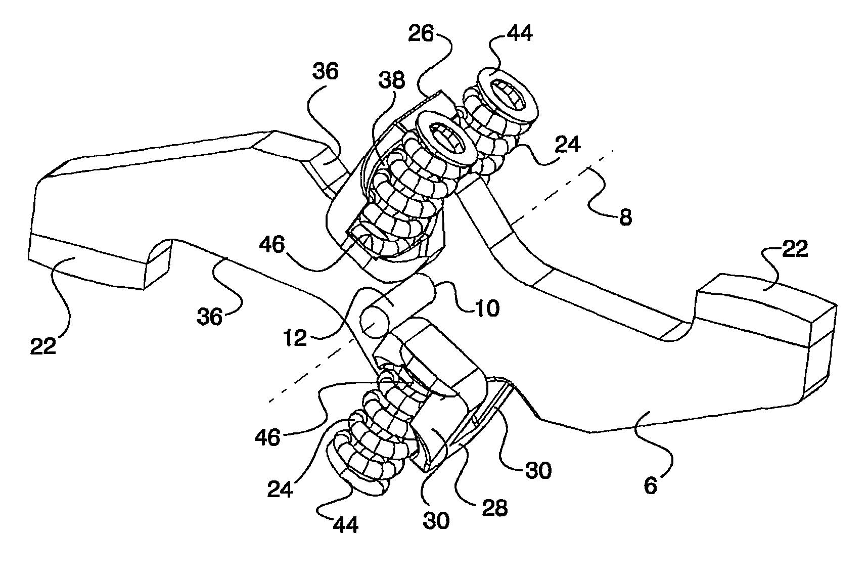
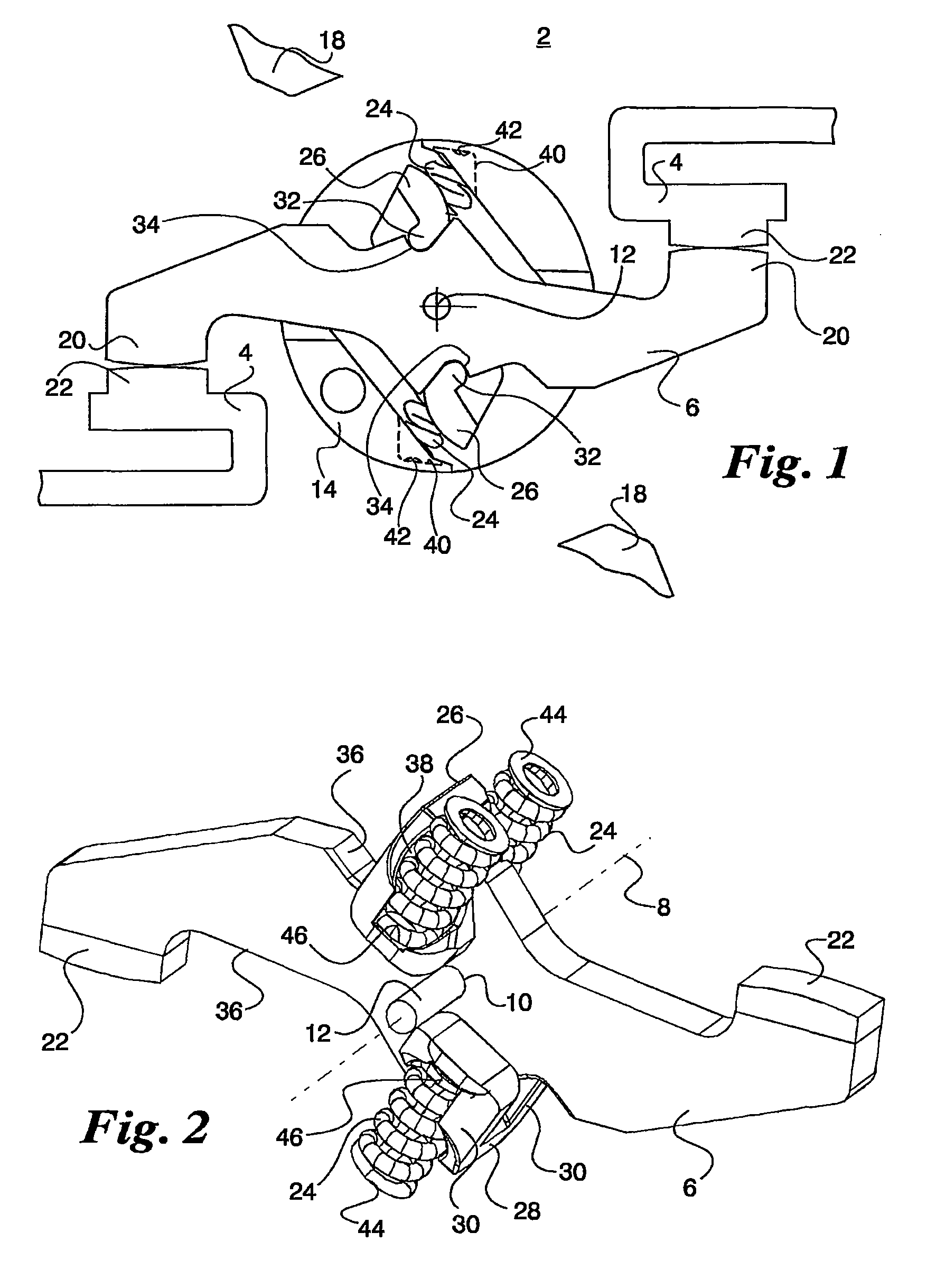
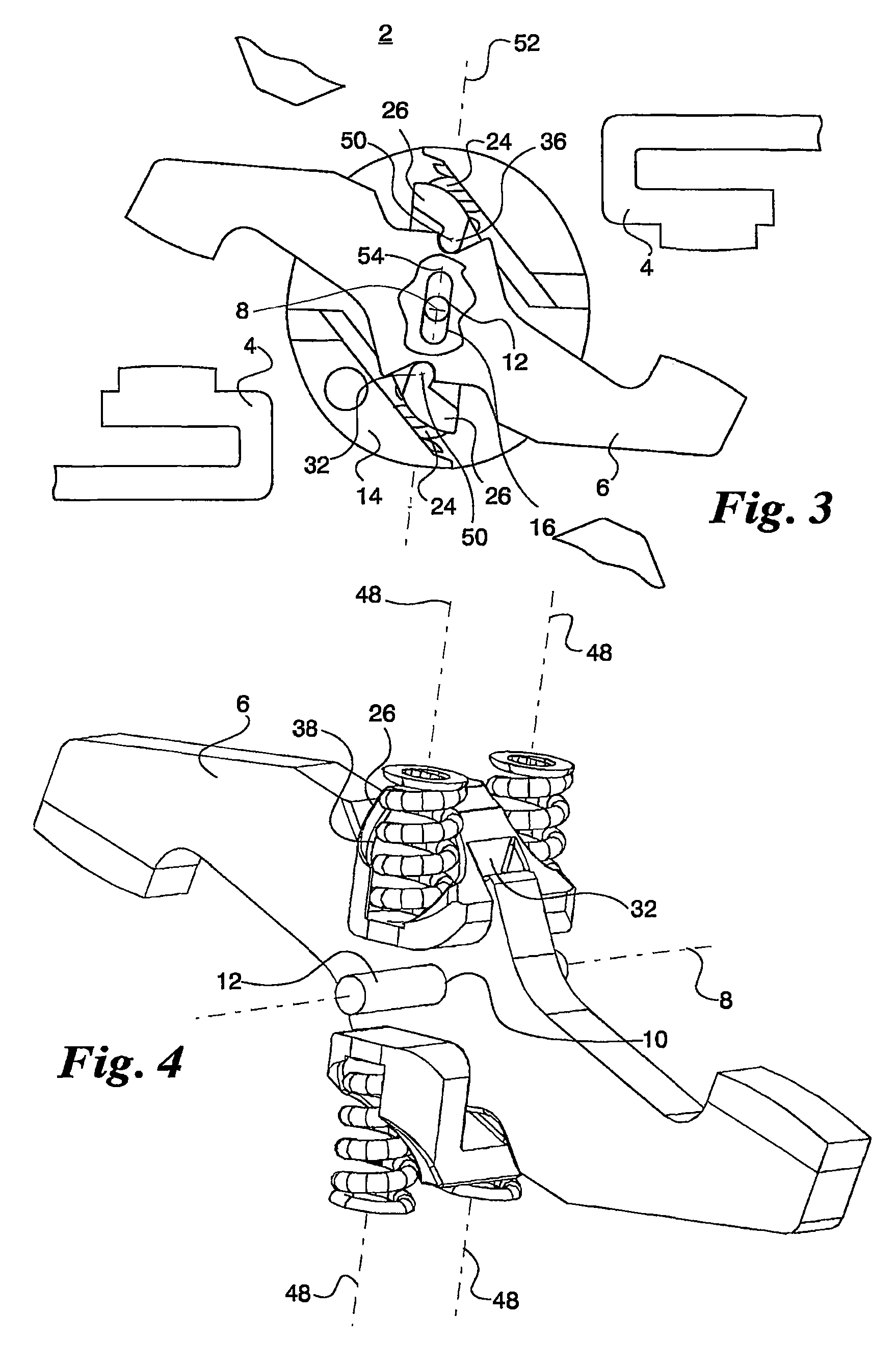
[0012]The contact system according to the invention combines the advantages of a tilting snap-action mechanism—in which the connection straight lines run through the tilting axis of the tilting point system in the tilting point—with the advantages of using pressure springs. The tilting axis coincides with the bearing axis of the rotary contact bridge. No appreciable friction losses occur in the tilting snap-action mechanism made up of the rotary contact bridge, the contact pressure springs, the rockers and the breaker shaft segment. The transverse load of the contact force springs, which increases the tolerance, is largely avoided. This results in greater reproducibility of the tilting behavior of the contact system and thus in greater reliability for the planning of the installation that is to be protected with the power circuit breaker. In conjunction with the rockers, the contact force springs configured as pressure springs create a space-saving arrangement inside the breaker shaft segment. The bearing of the breaker shaft in a slot allows an uncomplicated compensation of the on-position of the rotary contact bridge in case of asymmetrical contact erosion of the contact surfaces associated with the rotary contact bridge or of the fixed contacts. The lengthwise extension of the slot bearing parallel to or at an acute angle relative to the tilting point plane of the tilting snap-action mechanism prevents de-stabilization of the contact system in the tilting point.
[0013]Holding the contact force springs on the contact bridge side in receiving bores of the rockers saves additional installation space, particularly so when the rocker webs provided with the receiving bores extend laterally beyond the rotary contact bridge. In an advantageous manner, the ends of the contact force springs that are far from the contact bridge are affixed by holding nubs and / or holding depressions formed in the breaker shaft segment.

Problems solved by technology

A drawback of this is the unsatisfactory reproducibility of the dynamic tilting behavior of the contact system due to the frictional work that occurs between the pins and the control cams, due to the compressive forces on the free spring ends that are not directed towards the tilting axis and due to the tangential forces that act upon the sliding elements.
Transferring such a tilting snap-action mechanism to a contact system with a rotary contact bridge would detrimentally result in an enlargement of the contact system because of the working volume needed for the tension springs.

Method used


Image

  • Electrodynamically tilting contact system for power circuit breakers
  • Electrodynamically tilting contact system for power circuit breakers
  • Electrodynamically tilting contact system for power circuit breakers

Examples


Embodiment Construction

[0019]The contact system 2 according to the invention shown for a pole of a multipolar power circuit breaker comprises two fixed contacts 4 across from each other and a rotary contact bridge 6. This rotary contact bridge 6 is pivotably mounted in its rotation-symmetrical axis 8 by means of a circular bearing bore 10 on a cylindrical bearing axis 12. The rotary contact bridge 6 protrudes on both sides out of a breaker shaft segment 14, whereby the bearing axis 12 lies with both of its ends in lateral slots 16 in the breaker shaft segment 14. The breaker shaft segment 14 is mounted with adjacent breaker shaft segments in a switching device housing 18 that is only indicated in a rudimentary form. The ends of the fixed contacts 4 and of the rotary contact bridge 6 have contact surfaces 20 and 22 respectively which, in the on-position according to FIG. 1, create a conductive connection between the two fixed contacts 4 under the effect of the force of two pairs of contact force springs 24...


PUM


Abstract

An electrodynamically tilting contact system for power circuit breakers includes an actuating shaft segment, a rotary contact bridge pivotally mounted therein and contact force springs that form components of a tilting snap-action mechanism, which holds the rotary contact bridge in a repulsed position after an electrodynamically effected repulsion of fixed contacts. Two rockers, while serving as an additional component of the tilting snap-action mechanism, are mounted on the rotary contact bridge in a manner that enables them to tilt. The contact force springs are supported between the actuating shaft segment and the rockers, whereby the spring longitudinal axes, the tilting axes of the rockers, and the rotational symmetry axis of the rotary contact bridge are located in the tilting point plane of the tilting snap-action mechanism. The rotary contact bridge is mounted in the actuating shaft segment via a bearing pin and an elongated hole bearing whose longitudinal axis, together with the tilting point plane, forms an, at most, acute angle perpendicular to the bearing pin.

Description

[0001]The invention relates to an electrodynamically tilting contact system for power circuit breakers, especially for current-limiting circuit breakers, in which a breaker shaft segment, a rotary contact bridge pivotably mounted therein and contact force springs constitute components of a tilting snap-action mechanism that holds the rotary contact bridge in a repulsed position after the fixed contacts have been electrodynamically repulsed.BACKGROUND[0002]German patent application DE 100 56 820 A1 discloses a contact system for each pole of a power circuit breaker having a rotary contact bridge that electrically connects or disconnects two fixed contacts that are positioned across from each other. The rotary contact bridge is float-mounted in a breaker shaft segment by means of two contact force springs configured as pressure springs. The contact force springs are mounted across from each other on both sides of the rotary contact bridge in bores made in the breaker shaft and, throug...

Claims


Application Information

Patent Timeline
Patent Type & Authority Patents(United States)
IPC IPC(8): H01H1/22H01H73/04H01H77/10
CPCH01H1/205H01H77/104H01H73/045
Inventor HANDLER, KURTKREMERS, WOLFGANGPURSCH, HEINZSTAMMBERGER, HARTWIGZACHARIAS, ALBERT
Owner KLOCKNER-MOELLER GMBH
Learn More