CML to CMOS signal converter

a signal converter and cml technology, applied in the field of microelectronic circuits, can solve the problems of unaddressed problems in the performance of the signal conversion process, the inability to adapt to the transmission of high switching rate signals, and the inability to transmit signals in noisy environments,

Inactive Publication Date: 2008-07-01
GOOGLE LLC
View PDF7 Cites 12 Cited by
  • Summary
  • Abstract
  • Description
  • Claims
  • Application Information

AI Technical Summary

Problems solved by technology

The process of converting from one signaling protocol to another can be problematic, particularly when the change involves more than merely shifting the voltage levels of the signals between one voltage to another.
However, such single-ended rail-to-rail signals are not well adapted for transmitting high switching rate signals and / or transmitting signals within noisy environments.
However, heretofore, many difficulties remain unaddressed in the performance of this signal conversion process.
One key problem has been converting differential signals in such manner to produce rail-to-rail signals that have duty cycles compatible with the circuits that consume the signals.
When the consuming circuits operate at their best with rail-to-rail signals having a 50% duty cycle, signals having noticeably asymmetric duty cycles, e.g., 55%-45%, 65%-35% or worse, can lead to high bit error rates, or require the transmission rate of the data carried thereby to be lowered.
However, the circuitry applied to the task is cumbersome, requires a relatively large area of a semiconductor chip to implement and consumes much power.

Method used


Image

  • CML to CMOS signal converter
  • CML to CMOS signal converter
  • CML to CMOS signal converter

Examples


Embodiment Construction

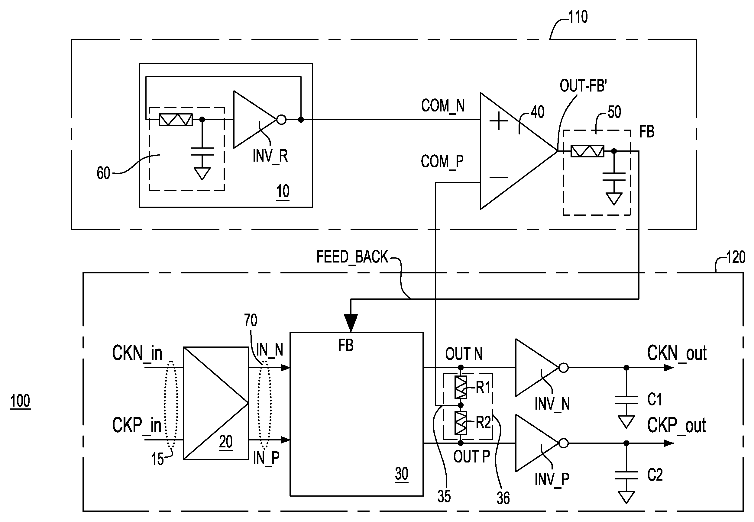
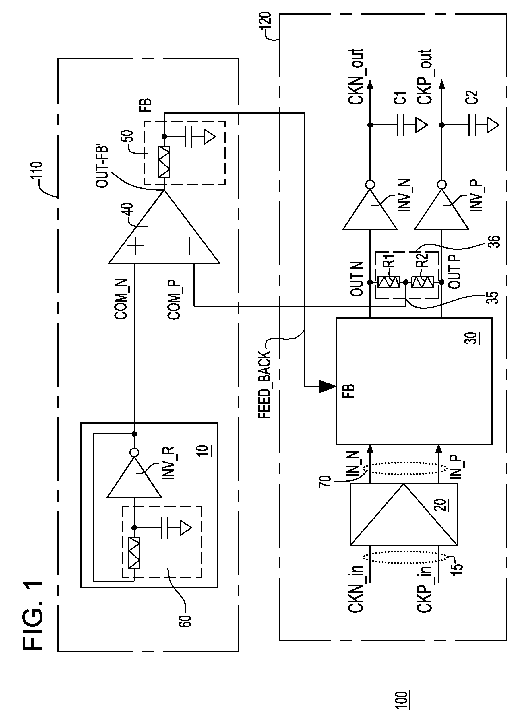
[0014]FIG. 1 is a block and schematic diagram of a signal regenerator 100, preferably employed as a clock converter circuit, in accordance with an embodiment of the invention. Using such circuit, a differentially transmitted non-return-to-zero (“NRZ”) clock signal, transmitted as the signal pair CKN_in and CKP_in, is converted into a single-ended rail-to-rail logic signal CKN_out. The circuit also outputs a second single-ended rail-to-rail logic signal CKP_out, which is complementary to CKN_out. In a particular preferred embodiment, the differentially transmitted signals are transmitted in accordance with a current mode logic (“CML”) signaling protocol, and the rail-to-rail logic signals are CMOS logic signals. However, the differentially transmitted signals need not be in accordance with CML signaling protocol, as other differential signaling protocols are available, and the rail-to-rail logic signals outputted by the signal regenerator 100 can be in accordance with other rail-to-r...


PUM


Abstract

A signal regenerator is provided which includes a common mode reference generator and a signal converter circuit. A common mode reference voltage level is generated which is variable in relation to at least one of a process used to fabricate the common mode reference generator, a level of a power supply voltage provided to the common mode reference generator or a temperature at which the common mode reference generator is operated. A signal converter circuit receives a differentially transmitted signal pair including a first input signal and a second input signal and outputs a single-ended output signal representing information carried by the differentially transmitted signal pair. Using a feedback signal from the common mode reference generator, a feedback control block controls a common mode level of the single-ended output signal in accordance with the common mode reference voltage level.

Description

BACKGROUND OF THE INVENTION[0001]The present invention relates to microelectronic circuits, especially those which are capable of converting signals from one signaling protocol, e.g., from a pair of differentially transmitted signals, to another signaling protocol, such as a signaling protocol in which one or more single-ended signals are transmitted.[0002]Microelectronic circuits of various types of required to convert certain signals that are transmitted in accordance with one signaling protocol into different signals that correspond to a different signaling protocol. The process of converting from one signaling protocol to another can be problematic, particularly when the change involves more than merely shifting the voltage levels of the signals between one voltage to another. Some signaling protocols produce single-ended CMOS logic or TTL logic-type signals which have rail-to-rail signal swings which are readily usable by complementary metal oxide semiconductor (“CMOS”) logic c...

Claims


Application Information

Patent Timeline
Patent Type & Authority Patents(United States)
IPC IPC(8): H03K17/16
CPCH03K19/018528
Inventor HSU, LOUIS L.GANGASANI, GAUTAMSORNA, MICHAEL A.ZIER, STEVEN J.
Owner GOOGLE LLC
Why Eureka
Try Eureka