Voltage-controlled oscillator circuit and PLL circuit
a voltage control and oscillator circuit technology, applied in pulse automatic control, pulse generation by logic circuits, pulse techniques, etc., can solve the problems of limiting improvement of jitter performance, increasing noise sources, etc., and achieving the effect of simplifying structure and not increasing circuit scale and power consumption
- Summary
- Abstract
- Description
- Claims
- Application Information
AI Technical Summary
Benefits of technology
Problems solved by technology
Method used
Image
Examples
first embodiment
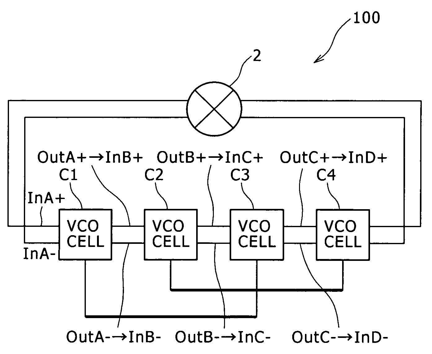
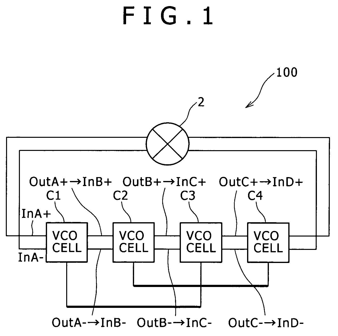
[0068]FIG. 1 is a block diagram of assistance in explaining an oscillator circuit according to a
[0069]An oscillator circuit 100 is a voltage-controlled oscillator (VCO). The oscillator circuit 100 changes the frequency of an oscillating signal according to a control voltage signal corresponding to a phase difference between a reference signal and a feedback signal.
[0070]The oscillator circuit 100 includes four VCO cells C1 to C4 having a same internal configuration, and an inverting unit 2 for inverting differential signal lines connected to the VCO cell C1 and the VCO cell C4.
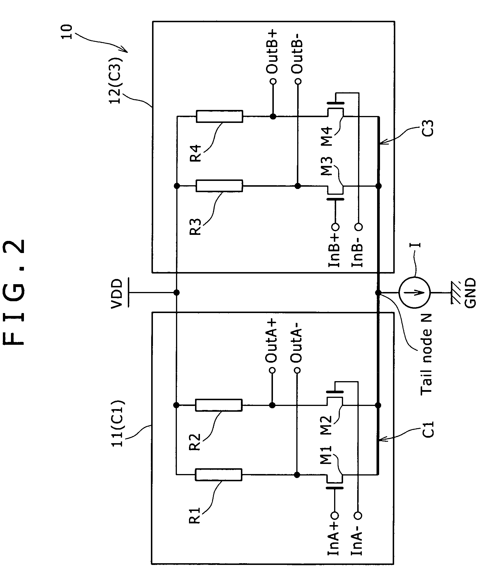
[0071]The tail nodes (to be described later) of the VCO cell C1 and the VCO cell C3 are connected to each other. The tail nodes of the VCO cell C2 and the VCO cell C4 are connected to each other.
[0072]The VCO cells C1 to C4 are cascaded in a plurality of stages in the form of a ring. The output terminals of the VCO cell C1 are connected to the input terminals of the VCO cell C2. The output terminals of the VCO...
second embodiment
[0102]an oscillator circuit will next be described.
[0103]Description in the following will be made of oscillator circuits 100b and 100c according to the second embodiment, centering on differences from the foregoing first embodiment, and description of similar items will be omitted.
[0104]FIG. 6 is a block diagram showing an oscillator circuit according to the second embodiment.
[0105]The oscillator circuit 100b according to the second embodiment is different from the oscillator circuit 100 according to the first embodiment in terms of combinations of VCO cells having tail nodes connected to each other.
[0106]The oscillator circuit 100b has VCO cells C1, C2, C3, C4, C5, and C6.
[0107]Letting N be the number of VCO cells (N is an even number of more than one), in the oscillator circuit 100b, the tail nodes of two VCO cells at an interval of N / 2 stages are connected to each other. Specifically, the tail nodes of the VCO cell C1 and the VCO cell C4 are connected to each other; the tail nod...
third embodiment
[0112]an oscillator circuit will next be described.
[0113]Description in the following will be made of an oscillator circuit 100d according to the third embodiment, centering on differences from the foregoing first embodiment, and description of similar items will be omitted.
[0114]FIG. 8 is a block diagram showing the oscillator circuit according to the third embodiment.
[0115]The oscillator circuit 100d according to the third embodiment is different from the oscillator circuit 100 according to the first embodiment and the oscillator circuit 100b according to the second embodiment in that the oscillator circuit 100d according to the third embodiment uses VCOs in an odd number of stages (an odd number of VCOs).
[0116]The oscillator circuit 100d includes: VCO cells C1, C2, and C3; a capacitance Ca1 disposed between the tail nodes of the VCO cells C1 and C2; a capacitance Ca2 disposed between the tail nodes of the VCO cells C2 and C3; and a capacitance Ca3 disposed between the tail nodes ...
PUM
 Abstract
Description
Claims
Application Information
 - R&D
- Intellectual Property
- Life Sciences
- Materials
- Tech Scout
- Unparalleled Data Quality
- Higher Quality Content
- 60% Fewer Hallucinations
Browse by: Latest US Patents, China's latest patents, Technical Efficacy Thesaurus, Application Domain, Technology Topic, Popular Technical Reports.
© 2025 PatSnap. All rights reserved.Legal|Privacy policy|Modern Slavery Act Transparency Statement|Sitemap|About US| Contact US: help@patsnap.com


