
Tubular capacitor with variable capacitance and dielectrically elongated inner electrode for NMR applications

a tubular capacitor and dielectrically elongated inner electrode technology, applied in mechanically variable capacitors, variable capacitors, magnetic measurements, etc., can solve the problem of limiting the quality of the resulting nmr spectra, achieve good nmr spectra, prevent high voltage sparkover, and facilitate clamping

Active Publication Date: 2008-07-01
BRUKER SWITZERLAND AG
View PDF11 Cites 5 Cited by
  • Summary
  • Abstract
  • Description
  • Claims
  • Application Information

AI Technical Summary

Benefits of technology

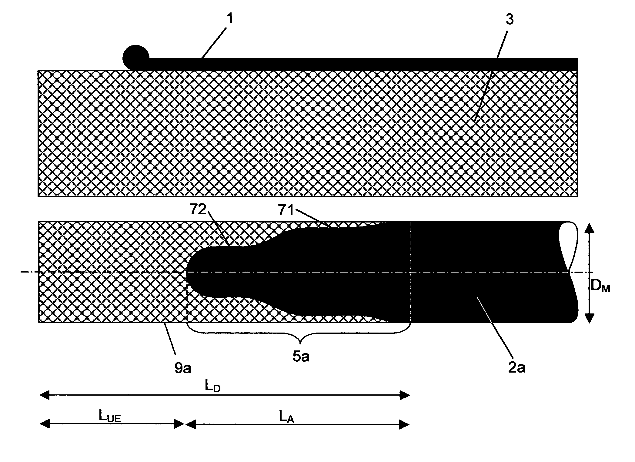
The present invention is about a tubular capacitor used in a nuclear magnetic resonance (NMR) probe head. The invention addresses the problem of high voltage sparkovers in conventional tubular capacitors. The invention introduces a new design that eliminates high voltage sparkovers in the region of the narrow gap between the cylindrical tube and the metallic rod. The new design includes a rod of dielectric material that is extended in an axial direction by a metallic rod. The end of the metallic rod has a rounded end part that prevents sharp transitions and reduces the tendency for high voltage sparkovers. The dielectric material has a higher dielectric strength than air, which makes it a better insulator. The new design also includes a sealingly connected rod of dielectric material that improves the dielectric strength at the connecting surface. The invention also mentions the use of a specific dielectric material that has a high dielectric strength and a relative dielectric constant between 1.3 and 5. The invention also includes a method for connecting the rod of dielectric material to the end part of the metallic rod to improve the dielectric strength.

Problems solved by technology

For this reason, the high voltage resistance (or dielectric strength) of the capacitive tuning elements limits the quality of the resulting NMR spectra.

Method used


Image

  • Tubular capacitor with variable capacitance and dielectrically elongated inner electrode for NMR applications
  • Tubular capacitor with variable capacitance and dielectrically elongated inner electrode for NMR applications
  • Tubular capacitor with variable capacitance and dielectrically elongated inner electrode for NMR applications

Examples


Embodiment Construction

[0039]Current NMR spectrometers almost exclusively use short RF pulses or precisely defined groups of RF pulses to excite the magnetic spins in the measuring sample. The resulting signal is called FID (Free Induction Decay) from which the desired NMR spectrum is subsequently calculated using fast Fourier transformation.

[0040]The measuring sample is excited using an RF resonator (RF=radio frequency) which is located within the NMR probe head, closely disposed about the measuring sample and tuned to the desired excitation frequency f0. The proton excitation frequency of today's NMR spectrometers is between 100 MHz and 900 MHz.

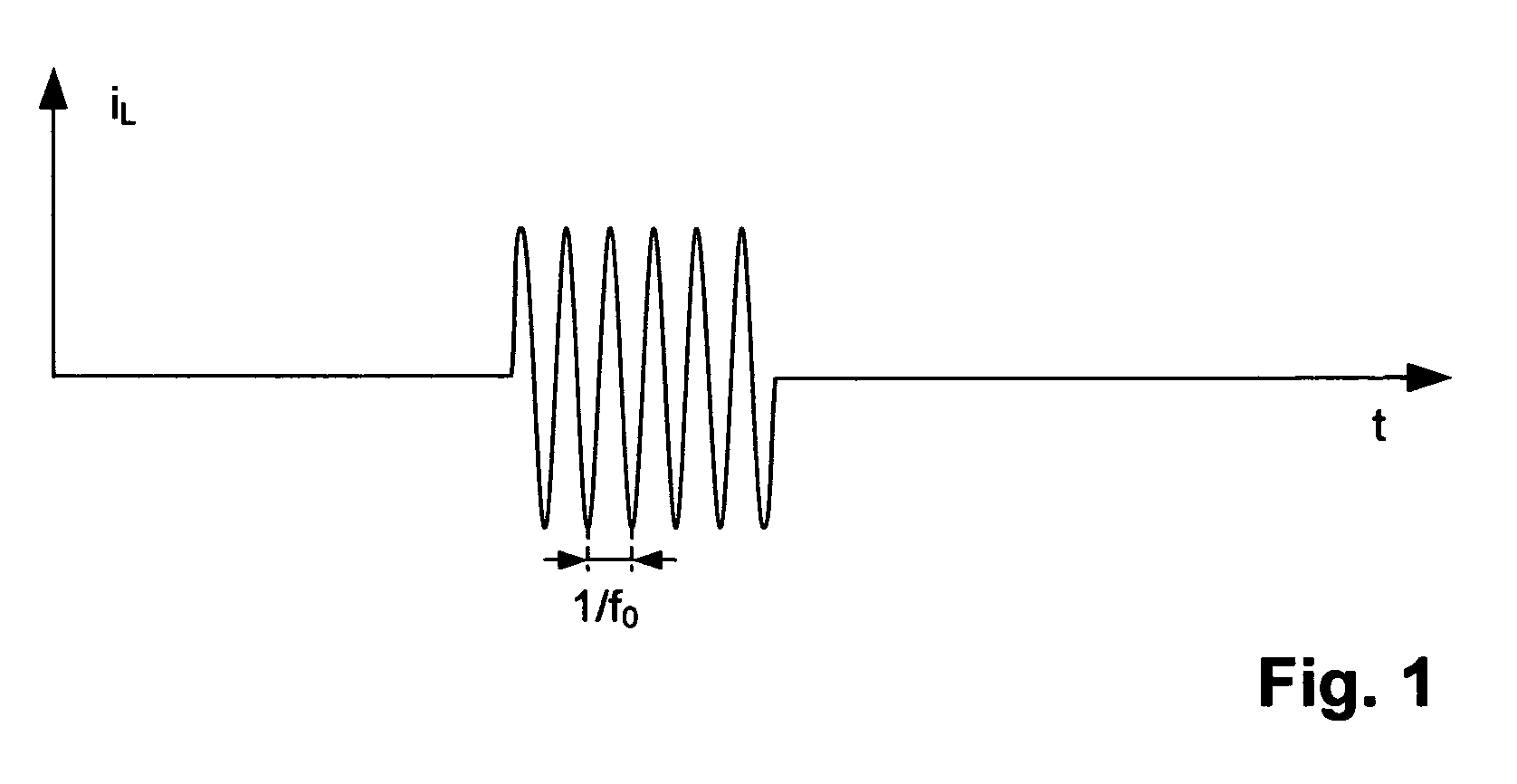
[0041]Short RF current pulses iL are fed into the RF resonator during the excitation process (FIG. 1). This produces short magnetic RF field pulses which excite the spin system.

[0042]The RF field pulses must be as short as possible in order to excite the overall NMR spectrum simultaneously and as uniformly as possible, and also have a sufficiently high RF field a...


PUM


Abstract

A tubular capacitor with variable capacitance, including a cylindrical tube (3) of dielectric material, a metallic outer electrode (1) which surrounds the cylindrical tube (3), and an inner electrode which can axially move in the inner bore (41) of the cylindrical tube (3) and which abuts the inner bore (41), wherein the inner electrode includes a metallic rod (2; 2a; 2b; 2c), is characterized in that the metallic rod (2; 2a; 2b; 2c) is axially extended at its end (5′), located in the inner bore (41) of the cylindrical tube (3), using a rod (9; 9a; 9b; 9c) of dielectric material. The inventive tubular capacitor has an increased dielectric strength and improves the resolution of NMR spectrometers.

Description

[0001]This application claims Paris Convention priority of DE 10 2005 046 039.9 filed Sep. 27, 2005 the complete disclosure of which is hereby incorporated by reference.BACKGROUND OF THE INVENTION[0002]The invention concerns a tubular capacitor with variable capacitance comprising a cylindrical tube of dielectric material, a metallic outer electrode which surrounds the cylindrical tube, and an inner electrode which can axially move in the inner bore of the cylindrical tube and which abuts the inner bore, the inner electrode comprising a metallic rod.[0003]Tubular capacitors of this type are e.g. used in NMR spectroscopic systems as described in the company leaflet “Avance—The Pulse Of Innovation” by the company Bruker BioSpin AG, Fällanden, Switzerland, April 2004.[0004]Nuclear magnetic resonance (NMR) spectrometry is one of the most powerful methods of instrumental analytics and is used, in particular, in biological sciences and material research. A radio frequency (RF) resonator t...

Claims


Application Information

Patent Timeline
Patent Type & Authority Patents(United States)
IPC IPC(8): H01G5/04H01G4/06
CPCG01R33/3628H01G5/14H01G5/014
Inventor GROSSNIKLAUS, BEATMAREK, DANIELSEYDOUX, ROBERTOSCHETT, OSKAR
Owner BRUKER SWITZERLAND AG
Learn More