Gas turbine fuel preparation and introduction method

a gas turbine and fuel preparation technology, applied in the ignition of the turbine/propulsion engine, engine starters, lighting and heating apparatus, etc., can solve the problems of limited utilization of such gases, insufficient heating value to be used, and insufficient hydrogen in coke oven gases to be used in connection with lean premix combustion systems

Active Publication Date: 2008-07-08
PRAXAIR TECH INC
View PDF8 Cites 81 Cited by
  • Summary
  • Abstract
  • Description
  • Claims
  • Application Information

AI Technical Summary

Benefits of technology

[0006]The present invention provides a method of preparing and introducing fuel into combustors of the gas turbine. In accordance with the method, a hydrocarbon containing feed stream is introduced into a catalytic partial oxidation reactor along with an oxygen containing stream and a steam stream. The hydrocarbon containing feed stream comprises no less than about 15 percent by volume in a dry basis of hydrocarbons with at least two carbon atoms and / or at least about 3 percent by volume of olefins. The hydrocarbon feed stream, oxygen containing stream and steam stream are introduced into the catalytic partial oxidation reactor so that a reaction mixture is obtained, prior to contact with catalyst, having an oxygen to carbon ratio of between about 0.08 and about 0.25 and a water to carbon ratio of between about 0.05 and about 0.5.

Problems solved by technology

Blast furnace gases are typically blended with other gases in that they do not have sufficient heating value to be used alone.
Coke oven gases contain too much hydrogen to be used in connection with lean premix combustion systems.
While blending such gases will reduce the problems associated with thermal cracking, the degree to which such gases are blended also will act as a limitation on the utilization of such gases.
There are other offgases produced in refineries, for instance, sweet refinery gases and fluidic catalytic cracker offgases that similarly contain a high content of hydrocarbons with two or more carbon atoms and have the potential for thermal cracking.
Similar problems exist in using other types of offgases and byproducts produced in other chemical production facilities.
A further problem is that the makeup of such gases can vary over time and as such, their use as gas turbine fuel can be highly problematical.
Moreover, such treatment also dampens the effect of variability in the consistency of the hydrocarbon makeup of such gases.

Method used


Image

  • Gas turbine fuel preparation and introduction method
  • Gas turbine fuel preparation and introduction method
  • Gas turbine fuel preparation and introduction method

Examples


Embodiment Construction

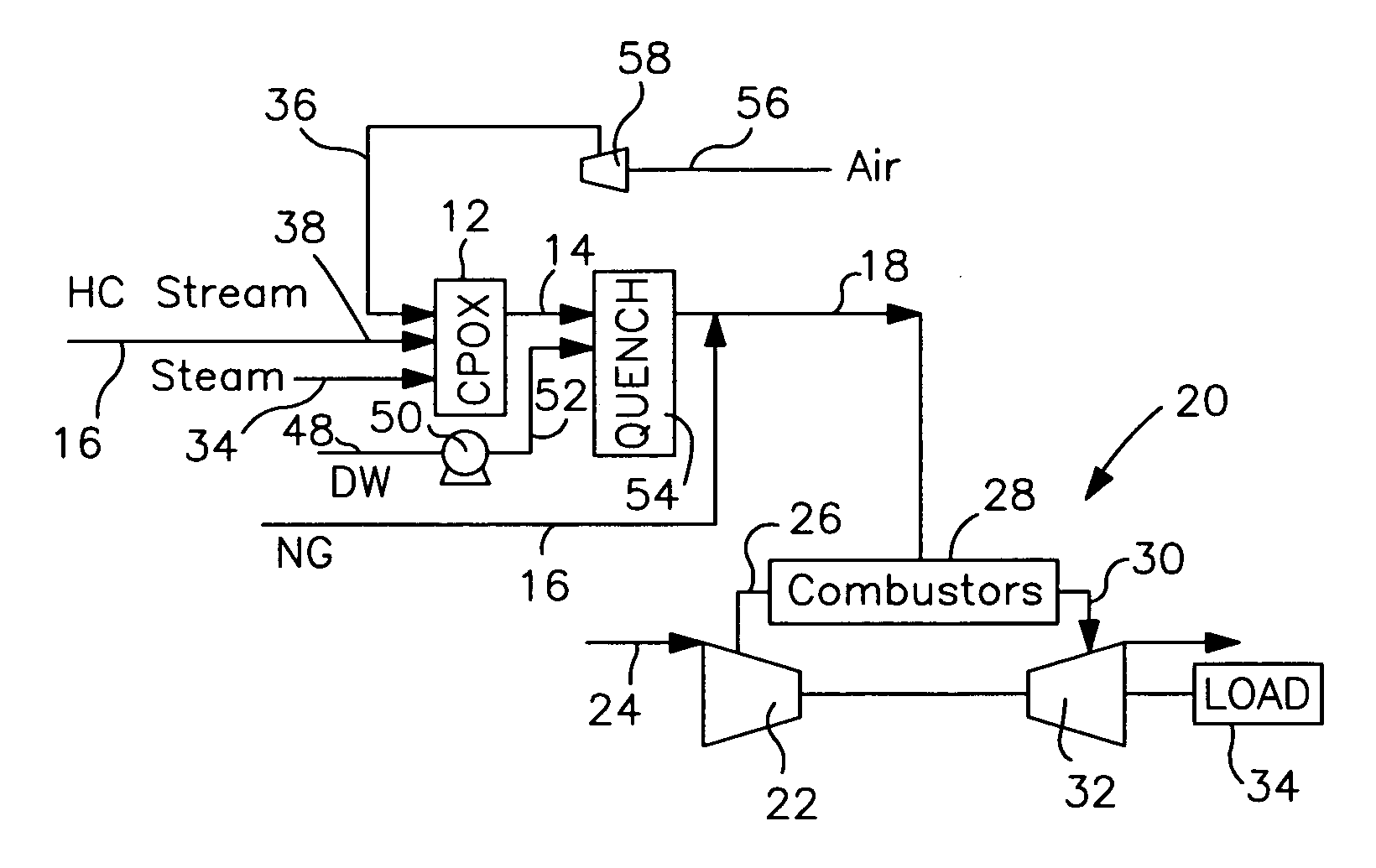
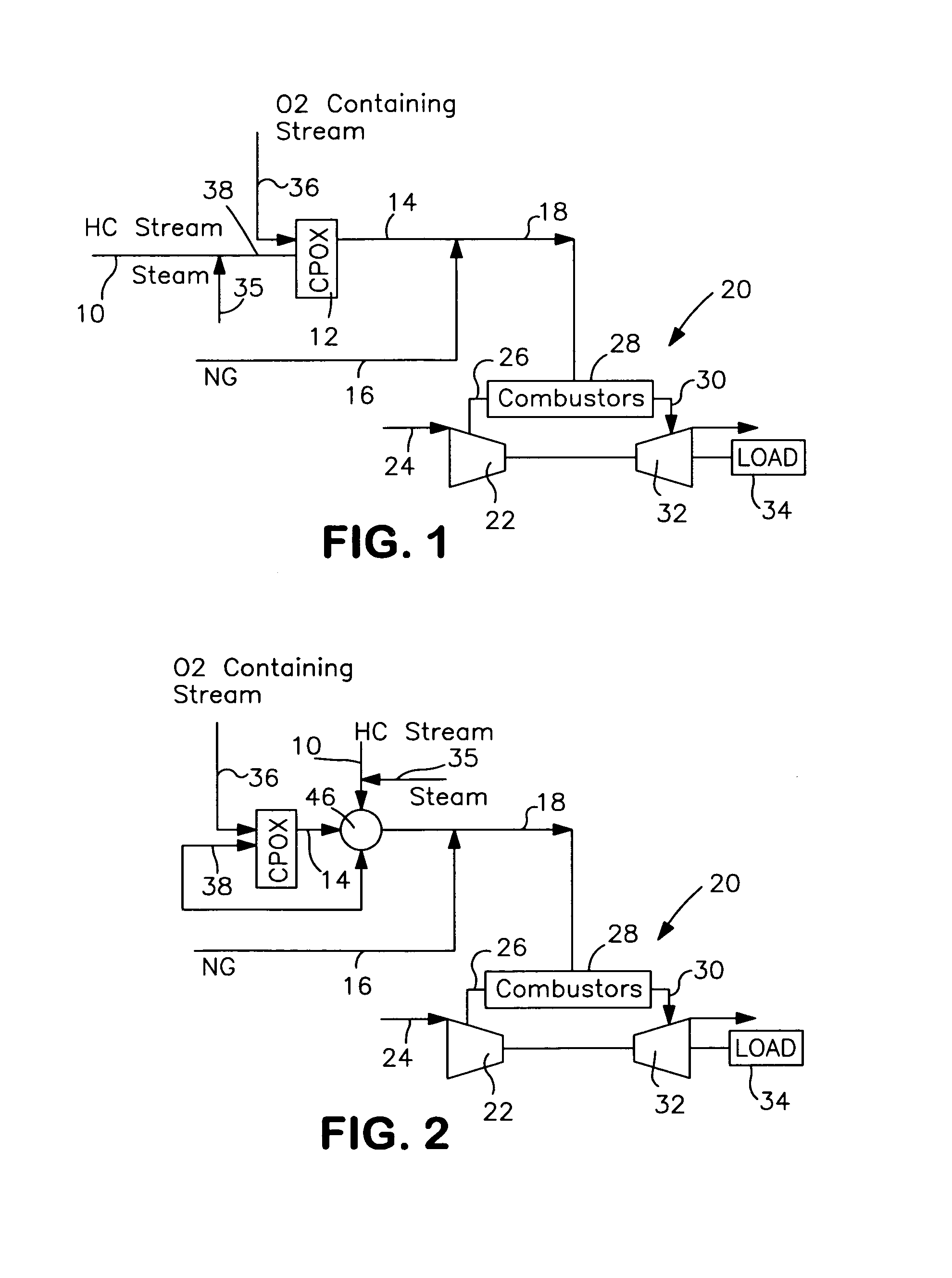
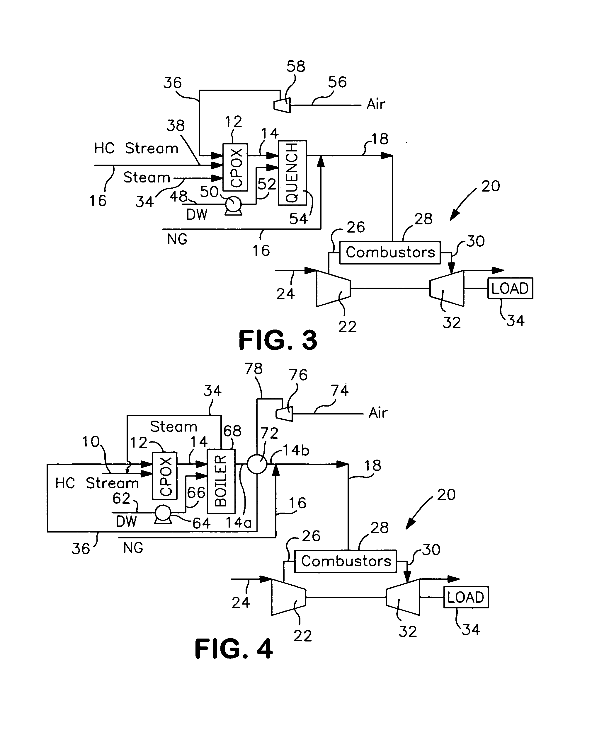
[0022]With reference to FIG. 1 a hydrocarbon containing feed stream 10 (“HC Stream”) is pretreated in a catalytic partial oxidation reactor 12 (“CPOX”) to produce a product stream 14 that is combined with a natural gas stream 16 (“NG”) or other fuel stream having a sufficient heating value, to form a fuel stream 18 that is introduced as fuel to a gas turbine 20.

[0023]Gas turbine 20 has a compression section 22 that can be a series of stages. Compressor section 22 compresses an air stream 24 to form a compressor air stream 26 that is heated by combustion of fuel stream 18 in combustors 28 to produce an exhaust stream 30. Exhaust stream 30 is introduced into a turbine section 32 that is connected to a load 35 that can be an electrical generator. Compressor section 22 and expander section 32 are mechanically coupled together. Combustors 28 can consist of combustors that are arranged around the compressor section 22 in a manner well known in the art. Expander 32 can be split into two in...


PUM


Abstract

Method of preparing and introducing fuel into the combustors of a gas turbine in which a hydrocarbon containing feed, oxygen and steam are introduced into a catalytic partial oxidation reactor to produce a product stream. The hydrocarbon containing feed contains no less than about 15 percent by volume on a dry basis of hydrocarbons with at least two carbon atoms and/or at least about 3 percent by volume of olefins. The reactant mixture formed of the hydrocarbon containing feed, oxygen and steam has an oxygen to carbon ratio of between about 0.08 and about 0.25 and a water to carbon ratio of between about 0.05 to about 0.5. The hydrocarbon containing feed is introduced into the reactor alone or with a steam at a temperature no greater than 600° C. and the product stream is produced at a temperature of between about 600° C. and 860° C. and contains less than about 0.5 percent of olefins and less than 10 percent of hydrocarbons with two or more carbon atoms on a dry basis. After cooling the product stream the product stream is introduced into the combustors of the gas turbine to form part or all of the fuel required to support combustion.

Description

FIELD OF THE INVENTION[0001]The present invention relates to a method of preparing and introducing fuel into combustors of a gas turbine. More particularly, the present invention relates to such a method in which a hydrocarbon containing feed stream is reacted with steam and oxygen in a catalytic partial oxidation reactor to reduce the heavy hydrocarbon content of such stream to acceptable levels prior to introduction into combustors of a gas turbine.BACKGROUND OF THE INVENTION[0002]Gas turbines are used in a variety of industrial settings to supply power to a load, generally an electrical generator. A gas turbine consists of a compressor to compress air and an expander to recover energy from the compressed air after having been heated. The compressed air is heated within a set of combustors located between the compressor and the expander.[0003]Gas turbines are designed to burn a variety of fuels such as natural gas, liquefied petroleum gas and synthesis gases containing hydrogen an...

Claims


Application Information

Patent Timeline
Patent Type & Authority Patents(United States)
IPC IPC(8): F02C6/18
CPCF02C3/20F02C7/22F02C9/26F02C9/48F23K5/002F23R3/286Y02T50/677F23K2401/10Y02T50/672F05D2270/08F23K2400/10Y02T50/60
Inventor DRNEVICH, RAYMOND FRANCISPAPAVASSILIOU, VASILIS
Owner PRAXAIR TECH INC
Why Eureka
Try Eureka