Fuel injection control system designed to eliminate overlap between multiple fuel injection events

a control system and fuel injection technology, applied in the direction of electric control, fuel injecting pumps, machines/engines, etc., can solve the problems of reducing the quantity of fuel injected into the engine, affecting the operation of the fuel injection control system, and the above type of fuel injection control system encountering another drawback, so as to eliminate overlap and eliminate overlap

Inactive Publication Date: 2008-07-08
DENSO CORP
View PDF12 Cites 12 Cited by
  • Summary
  • Abstract
  • Description
  • Claims
  • Application Information

AI Technical Summary

Benefits of technology

[0017]It is another object of the invention to provide a fuel injection control apparatus for a multi-cylinder internal combustion engine mounted in a vehicle which is designed to ensure the stability in running the vehicle at a minimized load on the apparatus.
[0018]According to one aspect of the invention, there is provided a fuel injection control apparatus which may be employed in automotive multi-cylinder diesel engine. The fuel injection control apparatus comprises: (a) injectors each of which, when energized, works to spray fuel into one of cylinders of an engine of a vehicle; (b) an operating condition determining circuit working to determine preselected operating conditions of the engine and the vehicle; and (c) a controller working to schedule execution of a sequence of multiple injections of the fuel into each of the cylinders through control of a corresponding one of the injectors in each operating cycle of the engine based on the operating conditions, as determined by the operating condition determining circuit. The controller determines whether an overlapping condition where events of any two of the injections scheduled to be executed in any two of the cylinders overlap in time with each other is met or not. When the overlapping condition is determined to be met, the controller determines which of the two of the injections overlapping each other should be rescheduled based on the operating condition of the vehicle, as determined by the operating condition determining circuit, and reschedules execution of one of the two of the injections, as determined to be rescheduled, so as to eliminate overlap with any of the events of the injections. Specifically, when at least one of the scheduled events of the sequence of injections to be executed in any one of the cylinders of the engine is in coincidence in time with that to be executed in another of the cylinders, the controller reschedules the execution of either of the overlapping events of the injections so as to eliminate the overlap with any of the events of the injections to be executed in the other cylinders without sacrificing running conditions of the vehicle, thereby avoiding the undesirable application of load on the apparatus or the delay in activating the injectors, as described above.
[0021]The controller works to monitor the operating condition of the vehicle, as determined by the operating condition determining circuit, to determine whether drive torque is required by the vehicle or not. When it is determined that the duration of one of the first sub-injection and the second sub-injection scheduled to be executed in one of the cylinders overlaps that of the main injection scheduled to be executed in another of the cylinders and that the drive torque is determined to be required by the vehicle, the controller reschedules the execution of the one of the first sub-injection and the second sub-injection, as determined as overlapping in the duration thereof with the main injection, so as to eliminate overlap with any of the events of the injections. Specifically, the controller prioritizes the execution of the main injection to ensure the stability in driving the vehicle.
[0022]The controller may monitor the operating condition of the vehicle, as determined by the operating condition determining circuit, to determine whether no drive torque is required by the vehicle or not. When it is determined that the duration of one of the main injection and the first sub-injection scheduled to be executed in one of the cylinders overlaps that of the second sub-injection scheduled to be executed in another of the cylinders and that no drive torque is determined to be required by the vehicle, the controller reschedules the execution of the one of the main injection and the first sub-injection, as determined as overlapping in the duration thereof with the second sub-injection, so as to eliminate overlap with any of the events of the injections.
[0024]The controller may work to monitor the operating condition of the vehicle, as determined by the operating condition determining circuit, to determine whether the vehicle is acceleration or not. When it is determined that the duration of the second sub-injection scheduled to be executed in one of the cylinders overlaps that of the first sub-injection scheduled to be executed in another of the cylinders and that the vehicle is accelerating, the controller reschedules the execution of the second sub-injection, as determined as overlapping in the duration thereof with the first sub-injection, so as to eliminate overlap with any of the events of the injections. Usually, when the vehicle is accelerating, the engine is required to produce the drive torque. Therefore, the controller prioritizes the execution of the first sub-injection to promote the combustion of the fuel in the engine.
[0025]When it is determined that the second sub-injection, as scheduled to be executed in one of the cylinders, overlaps that of one of the main injection, the first sub-injection, and the second sub-injection, as scheduled to be executed in another of the cylinders, the controller may omit at least a portion of the duration of the second sub-injection, as determined as overlapping that of the one, so as to eliminate overlap with the one, and also determine a duration of the second sub-injection scheduled to be executed subsequently in one of the cylinders so as to compensate for the omitted portion of the duration of the second sub-injection. Specifically, the controller compensates for a lack of the fuel arising from the omission of the duration of the second sub-injection in a subsequent event of the second sub-injection of the fuel into the engine.

Problems solved by technology

Particularly, when the peak current is supplied to the coils L1 and L3 simultaneously, it will drop in each of the coils L1 and L3, thus resulting in a delay in opening the injectors and a decrease in quantity of fuel injected into the engine.
The above type of fuel injection control system may, however, also encounters another drawback when the peak current is supplied to, for example, the coils L1 and L3 simultaneously.
Specifically, the simultaneous supply of the peak current to the coils L1 and L3 may cause the current which is about two times that when the peak current is applied to either one of the coils L1 and L3 to flow through the switching device TRk, the diode D1, and the common terminal To, thus resulting in a large load thereon.
The fuel injection control system, as taught in the above publication, eliminates the former problem, but has a difficulty in addressing the latter problem that devices other than the injectors are subjected to a large electrical load.
This is, however, objectionable to running conditions of the vehicle.
For instance, when drive torque is required to run the vehicle, but the execution of the main injection is cancelled, a difficulty may be encountered in ensuring the stability of running of the vehicle.
Additionally, when the execution of the pilot injection is cancelled during acceleration of the vehicle, it may result in knocking of the engine or increase in combustion noise.
Further, when a large amount of particulate matter (PM) is trapped in a diesel particulate filter (DPF), and the execution of the post injection is cancelled, it may result in a lack of burning the PM, thus decreasing the ability of emission gas purification.

Method used


Image

  • Fuel injection control system designed to eliminate overlap between multiple fuel injection events
  • Fuel injection control system designed to eliminate overlap between multiple fuel injection events
  • Fuel injection control system designed to eliminate overlap between multiple fuel injection events

Examples


Embodiment Construction

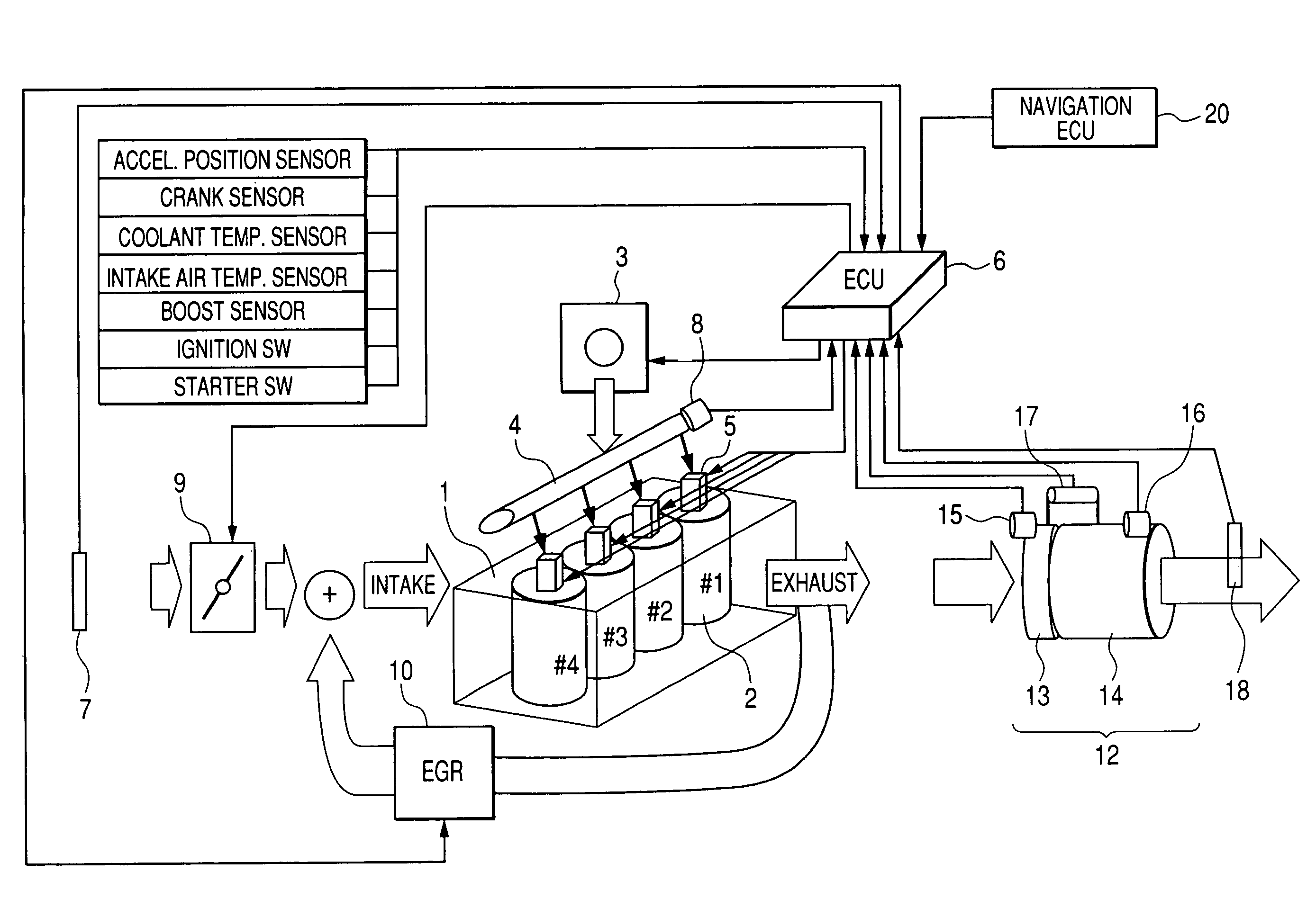
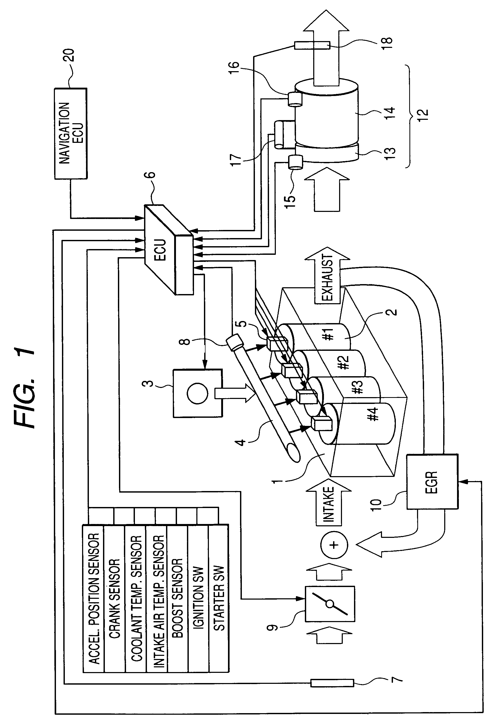
[0043]Referring to the drawings, wherein like reference numbers refer to like parts in several views, particularly to FIG. 1, there is shown a fuel injection control system according to the first embodiment of the invention which is engineered as a common rail fuel injection system for four-cylinder diesel engines to be mounted in automotive vehicles.

[0044]The fuel injection control system, as referred to herein, is designed to control an operation of a diesel engine 1 equipped with four cylinders 2 which will also be expressed below by #1 to #4. The fuel injection control system includes a high-pressure fuel pump 3, a common rail 4, injectors 5 one for each of the cylinders 2, an electronic control unit (ECU) 6, and a pressure sensor 8. The high-pressure fuel pump 3 works to feed fuel, as pumped out of a fuel tank, to the common rail 4. The common rail 4 stores therein the fuel at a controlled high pressure and supplies the fuel to each of the injectors 5.

[0045]The ECU 6 works to m...


PUM


Abstract

A fuel injection control system for a multi-cylinder internal combustion engine mounted in a vehicle is provided. The system works to schedule execution of a sequence of multiple injections of fuel into each of cylinders of the engine and determines whether events of any two of the injections scheduled to be executed in any two of the cylinders overlap in time with each other or not. If so, the system determines which of the two of the injections overlapping each other should be rescheduled based on operating condition of the vehicle and reschedules the execution of one of the two of the injections, as determined to be rescheduled, so as to eliminate overlap with any of the events of the injections. This avoids undesirable application of load on the system or the delay in activating fuel injectors which may arise from simultaneous activation of two of the injectors.

Description

CROSS REFERENCE TO RELATED DOCUMENT[0001]The present application claims the benefit of Japanese Patent Application No. 2006-74986 filed on Mar. 17, 2006, the disclosure of which is totally incorporated herein by reference.BACKGROUND OF THE INVENTION[0002]1. Technical Field of the Invention[0003]The present invention relates generally to a fuel injection control system such as a common rail system for automotive diesel engines which is designed to activate fuel injectors to spray jets of fuel into each of cylinders of the engine through a sequence of fuel injection events, and more particularly, to such a system designed to cancel or reschedule the execution of the fuel injection events so as to eliminate overlap in time between the fuel injection events.[0004]2. Background Art[0005]There are known fuel injection control systems such as common rail injection systems which are designed to open each of injectors installed in one of cylinders of a diesel engine several times in each eng...

Claims


Application Information

Patent Timeline
Patent Type & Authority Patents(United States)
IPC IPC(8): F02B5/00F02M51/00
CPCF02D41/0087F02D41/402F02D41/401Y02T10/44Y02T10/40
Inventor WATANABE, MITSURA
Owner DENSO CORP
Why Eureka
Try Eureka