Method and apparatus for preventing slug flow in pipelines

a technology of pipelines and gas or liquid slugs, applied in the direction of borehole/well accessories, sealing/packing, transportation and packaging, etc., can solve the problems of pipelines that are susceptible to slug formation, flowlines, and liquid slugs can increase in size, so as to prevent or reduce the build-up reduce the size of liquid or gas slugs, and minimize the risk of slug formation

Inactive Publication Date: 2008-07-08
BAKER HUGHES HLDG LLC
View PDF9 Cites 35 Cited by
  • Summary
  • Abstract
  • Description
  • Claims
  • Application Information

AI Technical Summary

Benefits of technology

[0013]This invention provides a system and method for minimizing the risk of slug formation in a flowline for land based or subsea oil well operations. In one embodiment, a liquid surface tension reducer, such as a foamant, is injected into the flowline or well to prevent or reduce the build up of liquid or gas slugs along a flow line. The foamant interacts with a two-phase production fluid, which may or may not include particulates, to substantially reduce the size of the liquid or gas slug and thereby minimize the formation of slugs along the flowline or in the riser. An exemplary system can include tanks for storing one or more foamants and one or more pumping systems for injecting or pumping the foamant(s) into a subsea wellhead, a subsea wellbore, or a flowline from one or more wellbores.

Problems solved by technology

Undersea pipelines, particularly those pipelines running from undersea production wells to loading facilities, commonly referred to as flowlines, can be susceptible to slug formation.
In many instances, the liquid slug can increase in size to an extent that partially or fully occludes the flow bore of the flow line or riser, either of which disrupts the flow of gas to the production facility.
Slugs in the flow line can create discontinuities in the pressure gradient across the flow line, which can markedly reduce production flow rates.
The sudden onrush of these liquid and gas slugs, which can alternate, can pose a severe threat to surface equipment and personnel.
As can be appreciated, the gas bubble can to some degree restrict the flow cross-sectional area at the high point, which can lead to an undesirable decrease in flow rates and / or an increase in back pressure.
Another problem arises when the gas bubble is released from the high point and flows along the pipeline.
As the gas slug moves up the riser toward the surface, the pressure head gradually decreases, which causes the gas to decompress and increase in size.
In some cases, gas slugs that are centimeters in diameter in the flow line can expand into diameters of several meters as they approach the surface, which can stress or overwhelm surface equipment.
Such devices can take up space on the deck of the surface facility.
Typically, however, the deck space on an offshore rig or similar facility can be exceedingly limited.
Moreover, gas slugs can cause corrosion in the pipe lines as well as make corrosion inhibition difficult.

Method used


Image

  • Method and apparatus for preventing slug flow in pipelines
  • Method and apparatus for preventing slug flow in pipelines
  • Method and apparatus for preventing slug flow in pipelines

Examples


Embodiment Construction

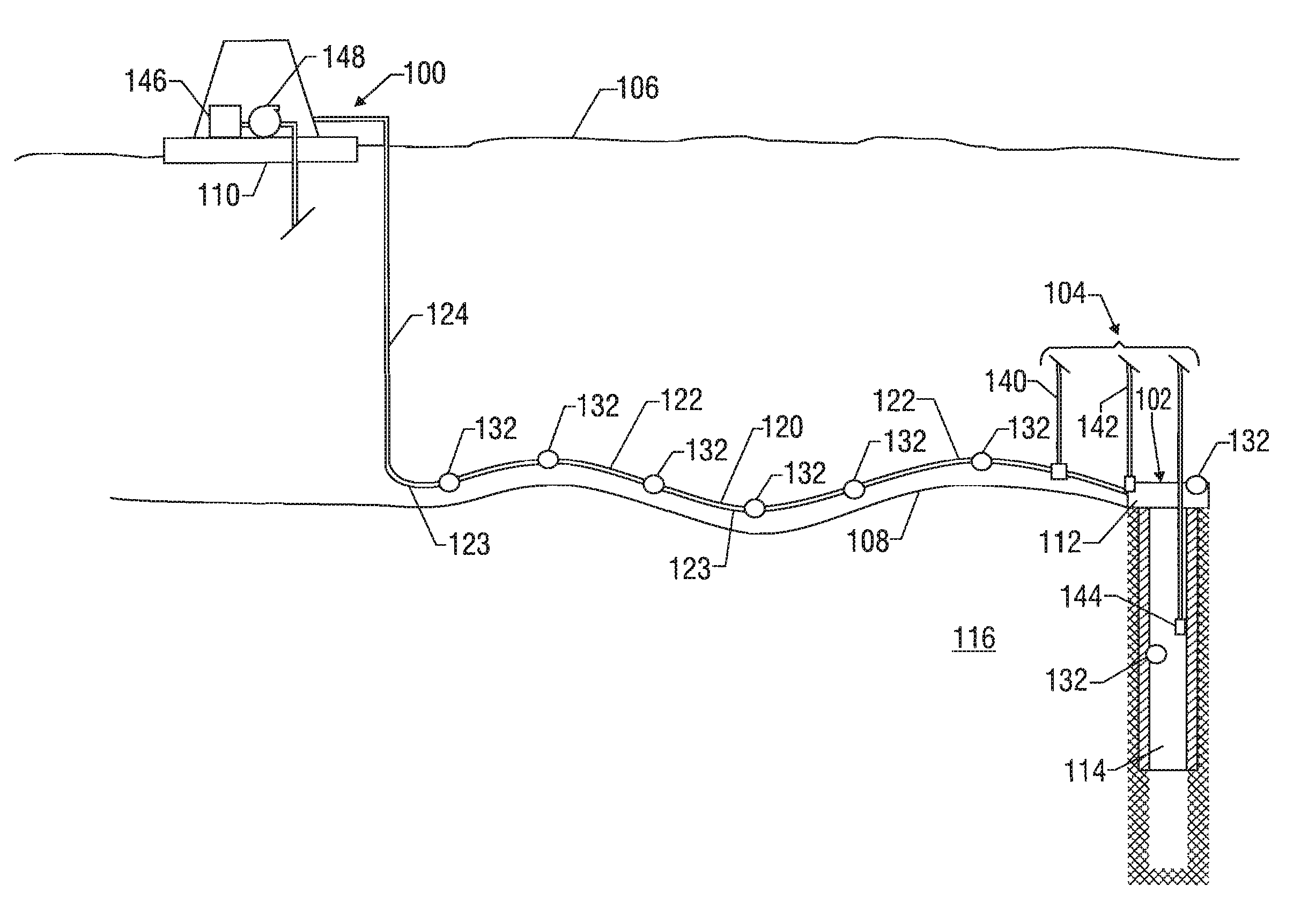
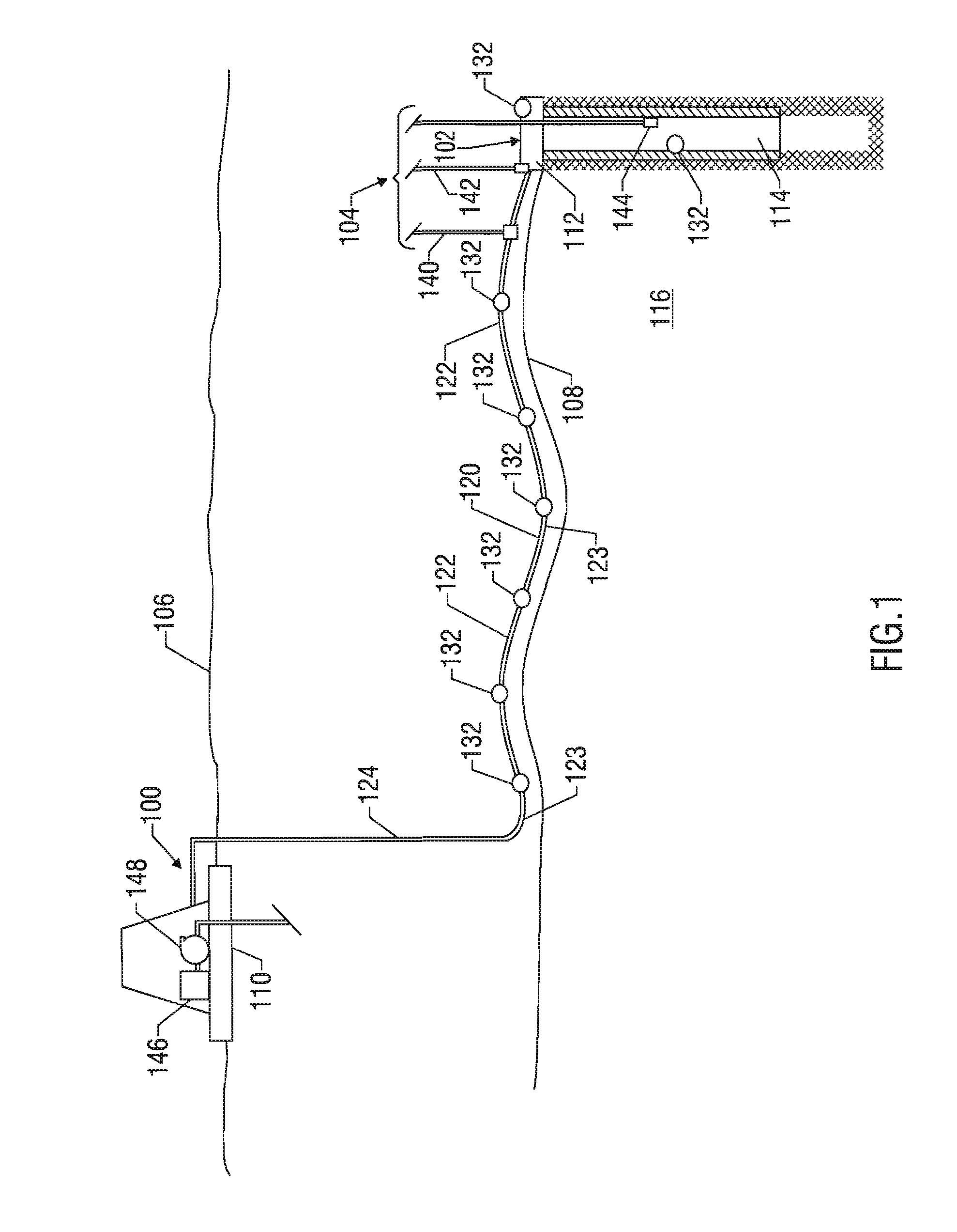
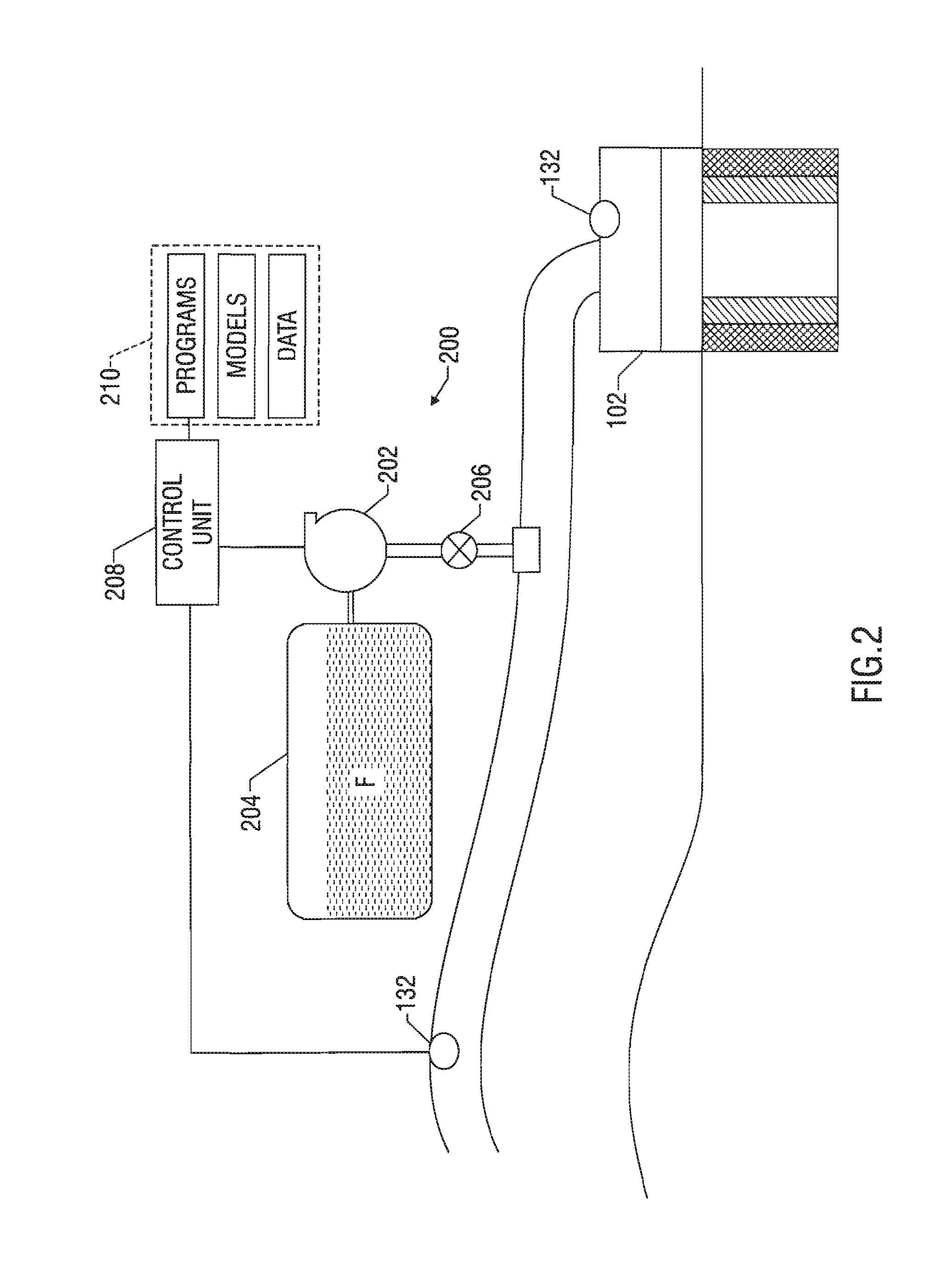
[0020]The present invention includes devices, systems and methods for inducing an annular flow regime along a pipeline or flowline by minimizing slug formation. In one exemplary application, the pipeline is a flowline that is an element of a subsea oil and gas production, collection, and shipping facility, including an offloading system, such as a buoy or platform offloading system. Product leads normally extend from subsea wells to a manifold from which flow lines bring the production fluid to a buoy or platform for transport. Such product flowlines have been metal pipes, sometimes with intermediate floatation devices located along the lengths of the product flowlines, to provide a suitable contour or configuration to the flowlines to avoid excessive loads resulting from the weight of the flowlines. In another exemplary application, the pipeline is land-based and receives production flow from a surface wellhead or other source.

[0021]The devices, systems and methods of the present i...


PUM


Abstract

Disclosed is a method and system for controlling the formation of liquid or gas slugs along a pipeline. In embodiments, an injection unit injects a liquid surface tension reducing agent, such as a foamant, into the pipeline upstream of the high point. A control unit can be used to control the injection unit. In certain arrangements, the control unit adjusts the injection of the agent based on measured parameters of interest. In embodiments where the control unit utilizes temperature measurements, one or more temperature sensors are positioned along the pipeline. The control unit utilizes the temperature measurements to determine whether a predetermined condition exists or a liquid or gas slug is present.

Description

[0001]This application takes priority from U.S. Provisional Application Ser. No. 60 / 633,715 filed on Dec. 6, 2004.BACKGROUND OF THE INVENTION[0002]1. Field of the Invention[0003]This invention relates to the controlling gas or liquid slugs in of pipelines and more particularly to controlling gas or liquid slugs in undersea pipelines.[0004]2. Background of the Art[0005]Pipelines are widely used in a variety of industries, allowing a large amount of material to be transported from one place to another. A variety of fluids, such as oil and / or gas, as well as particulate, and other small solids suspended in fluids, are transported cheaply and efficiently using underground pipelines. Pipelines can be subterranean, submarine, on the surface of the earth, and even suspended above the earth. Submarine pipelines especially carry enormous quantities of oil and gas products indispensable to energy-related industries, often under tremendous pressure and at low temperatures and at high flow rate...

Claims


Application Information

Patent Timeline
Patent Type & Authority Patents(United States)
IPC IPC(8): E21B43/01B65G53/58F17D1/17
CPCF17D1/17C09K8/52Y10T137/0357Y10T137/0391Y10T137/3003
Inventor RAMACHANDRAN, SUNDERGALLAGHER, CHRISTOPHER T.LOUDERMILK, MICHAEL D.YANG, JIANG
Owner BAKER HUGHES HLDG LLC
Why Eureka
Try Eureka