Control device for vehicular drive system

a control device and drive system technology, applied in the direction of electrical control, hybrid vehicles, gearing, etc., can solve the problems of deterioration of the fuel economy of the engine, the risk of deterioration of the shifting response of the transmission, and the shift system may suffer from a shifting shock, so as to reduce the required size of the electric motor and the required size of the drive system including the electric motor, the effect of improving fuel economy

Active Publication Date: 2008-07-08
TOYOTA JIDOSHA KK
View PDF25 Cites 17 Cited by
  • Summary
  • Abstract
  • Description
  • Claims
  • Application Information

AI Technical Summary

Benefits of technology

[0015]In the control device described above, the continuously-variable shifting control means is operable during a shifting control of the transmission portion for a stepping change of its speed ratio, for implementing a shifting control of the continuously-variable transmission portion in synchronization with the shifting control of the transmission portion, such that a speed ratio defined by the continuously-variable transmission portion and the transmission portion, that is, an overall speed ratio defined by a speed ratio of the continuously-variable transmission portion and the speed ratio of the transmission portion is continuously changed, that is, so as reduce an amount of a stepping change of the speed ratio due to a shifting action of the transmission portion. Accordingly, a stepping change of the speed of the engine before and after the shifting action of the transmission portion is reduced, and a shifting shock of the transmission portion is reduced. Further, the drive system as a whole is operable to function as a continuously variable transmission, so that the fuel economy of the vehicle is improved.
[0060]Preferably, the differential mechanism is placed in the non-differential state when a drive-force-related value of the vehicle has exceeded an upper output limit value provided for determining a high-output running state of the vehicle. In this case, when the required vehicle drive force or actual vehicle drive force has exceeded the upper output limit value, the output of the engine is transmitted to the drive wheel primarily through a mechanical power transmitting path, so that the maximum amount of electric energy that must be generated when the continuously-variable transmission portion is operated as an electrically controlled continuously variable transmission can be reduced, whereby the required size of the electric motor and the required size of the drive system including the electric motor can be reduced. The drive-force-related value is a parameter directly or indirectly relating to the drive force of the vehicle, such as an output torque of the engine, an output torque of the transmission, a drive torque of the drive wheel, and any other torque or rotary force in the power transmitting path, or an angle of opening of a throttle valve of the engine. The upper output limit value is predetermined to determine whether the vehicle is in the high-output running state.

Problems solved by technology

Accordingly, the drive system may suffer from a shifting shock, or suffer from deterioration of fuel economy of the engine due to a failure to control the engine speed along the highest-fuel-economy curve for the engine to provide a required torque.
Thus, the transmission has a risk of deteriorated shifting response.
For instance, when the transmission is commanded to effect a shift-down action upon depression of an accelerator pedal, the engine speed may not rise in a quick response to the depression of the accelerator pedal, leading to a possibility of a delayed rise (delayed initiation of increase) of the engine output.

Method used


Image

  • Control device for vehicular drive system
  • Control device for vehicular drive system
  • Control device for vehicular drive system

Examples


embodiment 1

[0105]Referring to the drawings, there will be described in detail the preferred embodiments of the present invention.

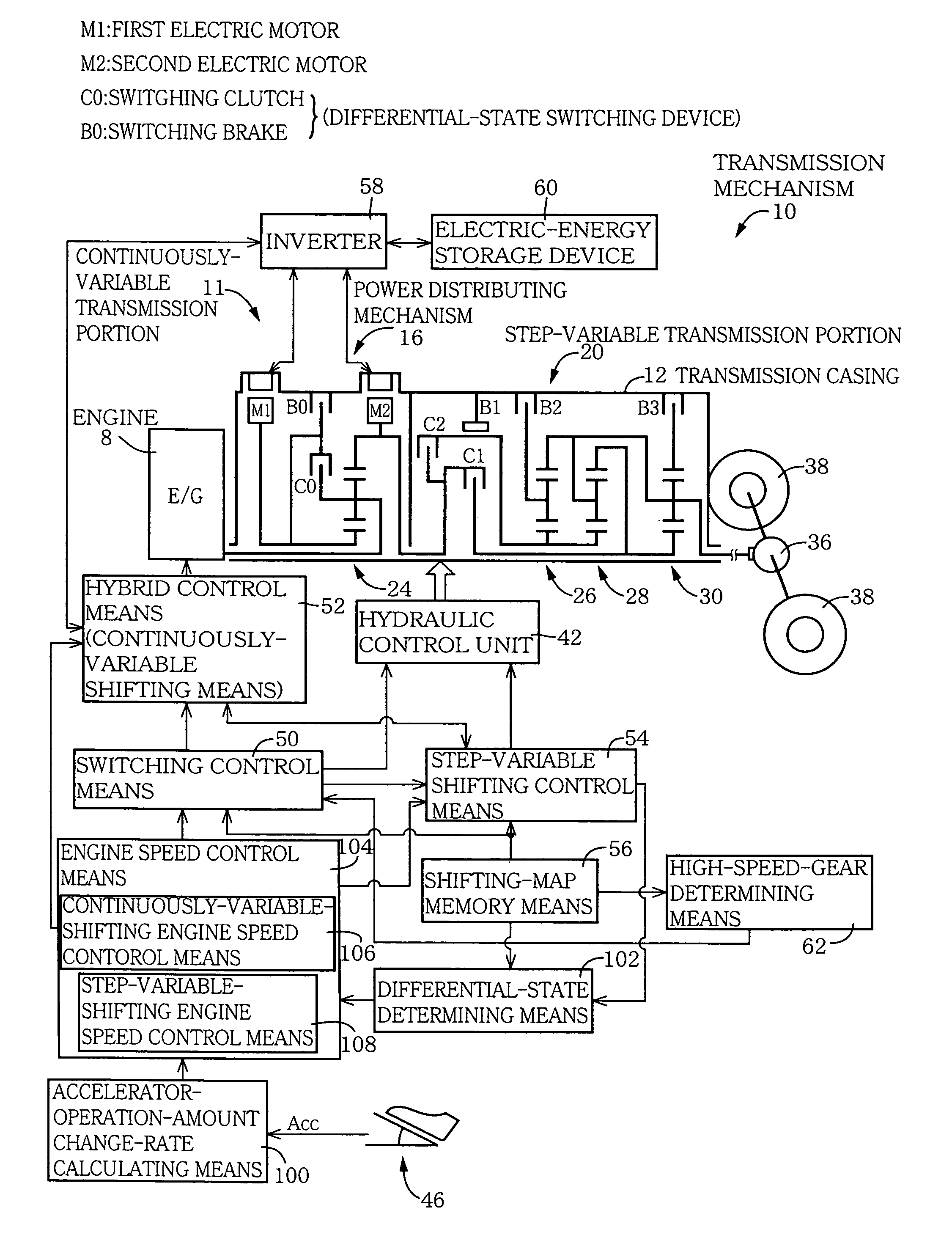
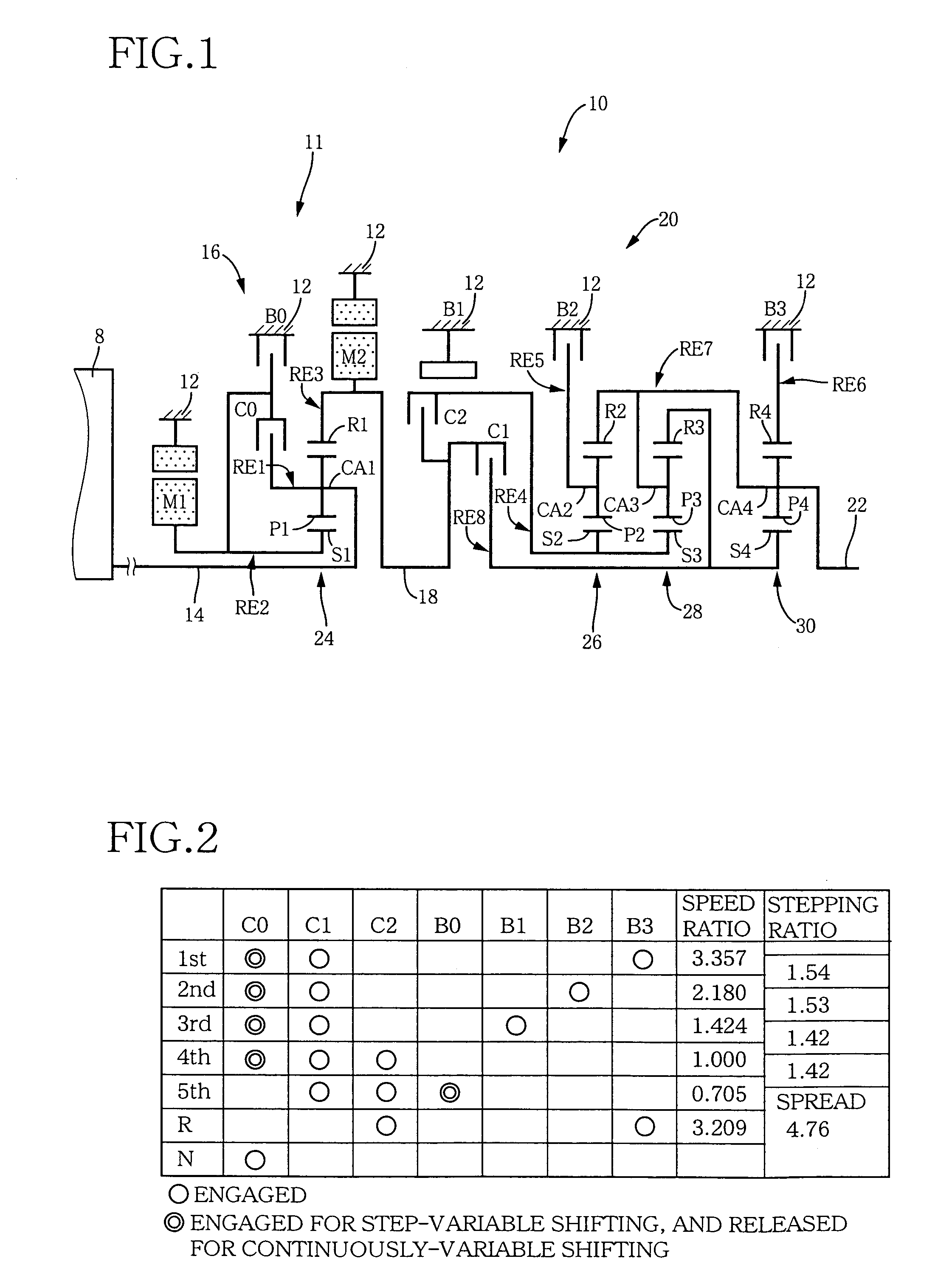
[0106]FIG. 1 is a schematic view explaining a transmission mechanism 10 constituting a part of a drive system for a hybrid vehicle, which drive system is controlled by a control device according to one embodiment of this invention. In FIG. 1, the transmission mechanism 10 includes: an input rotary member in the form of an input shaft 14 disposed on a common axis in a transmission casing 12 functioning as a stationary member attached to a body of the vehicle; a continuously-variable transmission portion 11 connected to the input shaft 14 either directly, or indirectly via a pulsation absorbing damper (vibration damping device) not shown; a step-variable or multiple-step transmission portion 20 disposed between the continuously-variable transmission portion 11 and drive wheels 38 (shown in FIG. 5) of the vehicle, and connected in series via a power transmitting member ...

embodiment 2

[0186]In the preceding embodiment, the hybrid control means 52 is arranged to implement the shifting control of the continuously-variable transmission portion 11 in synchronization with the shifting control of the step-variable transmission portion 20, that is, in the inertial phase in the process of the shifting action of the transmission portion 20, so that the total speed ratio γT of the transmission mechanism 10 is continuously changed before and after the shifting action of the step-variable transmission portion 20. The present embodiment provides some examples clarifying the shifting control of the continuously-variable transmission portion 11 which takes place in the inertial phase in the process of the shifting action of the step-variable transmission portion 20, for assuring a continuous change of the total speed ratio γT of the transmission mechanism 10 before and after the shifting action of the transmission portion 20.

[0187]In the preceding embodiment, the shifting contr...

embodiment 3

[0215]Referring to the schematic view of FIG. 19, there is shown an arrangement of a transmission mechanism 70 in another embodiment of this invention, and FIG. 20 a table indicating a relationship between the gear positions of the transmission mechanism 70 and different combinations of engaged states of the hydraulically operated frictional coupling devices for respectively establishing those gear positions, while FIG. 21 is a collinear chart for explaining a shifting operation of the transmission mechanism 70.

[0216]The transmission mechanism 70 includes the continuously-variable transmission portion 11 having the first electric motor M1, power distributing mechanism 16 and second electric motor M2, as in the preceding embodiments. The transmission mechanism 70 further includes a step-variable transmission portion 72 having three forward drive positions. The transmission portion 72 is disposed between the continuously-variable transmission portion 11 and the output shaft 22 and is ...


PUM


Abstract

Hybrid controller 52 for a vehicular drive system is operable during a shifting control of step-variable transmission portion 20 for a stepping change of its speed ratio, for changing a speed ratio of continuously-variable transmission portion 11, such that total speed ratio γT of transmission mechanism 10 defined by the speed ratio of the continuously-variable transmission portion 11 and the speed ratio of the step-variable transmission portion 20 is continuously changed, irrespective of the stepping change of the speed ratio of the step-variable transmission portion 20, so that an amount of stepping change of engine speed NE before and after a shifting action of the step-variable transmission portion 20 is reduced, and a shifting shock of the step-variable transmission portion 20 is reduced. The hybrid controller 52 permits the transmission mechanism 10 to function as a continuously variable transmission, thereby improving fuel economy of the vehicular drive system.

Description

FIELD OF THE INVENTION[0001]The present invention relates in general to a vehicular drive system including a differential mechanism which functions as a transmission having a differential function, and more particularly to techniques for controlling the speed ratio of one of the differential mechanism and an automatic transmission in relation to the speed ratio of the other.BACKGROUND ART[0002]There is known a drive system for a vehicle, which includes a differential mechanism functioning as a transmission having a differential function, and an automatic transmission operable in a step-variable shifting state, and which is arranged to transmit an output of a drive power source to drive wheels of the vehicle. Generally, the overall speed ratio of the vehicular drive system of this type is determined by the speed ratios of those two transmission mechanisms.[0003]As an example of the differential mechanism functioning as a transmission having a differential function, there is known a d...

Claims


Application Information

Patent Timeline
Patent Type & Authority Patents(United States)
IPC IPC(8): B60W10/04B60W10/10B60K1/02B60K6/365B60K6/445B60K6/547B60L50/16B60W30/18F02D29/02F02D41/02F16H3/72F16H61/02F16H61/04
CPCB60K6/445B60K6/547B60W30/19F02D41/023F16H3/728B60K6/365B60K1/02Y10T477/679B60W10/06B60W10/08B60W10/105B60W20/00F02D2400/12F16H61/0437F16H2037/0873F16H2061/6601F16H2061/6603F16H2200/0043F16H2200/0047F16H2200/201F16H2200/2012Y02T10/6286Y02T10/6239Y10S903/93Y10T477/675Y10T477/6217Y10T477/619Y10T477/33B60L15/20B60L2240/421B60L2240/423B60L2240/441B60L2240/443B60L2240/486B60L2240/507B60L2250/12B60L2260/26B60L2270/145Y02T10/72B60L50/61B60L50/16Y02T10/62Y02T10/64Y02T10/7072Y02T10/70F16H61/02B60K6/20B60K6/50B60W10/02B60W20/30
Inventor TABATA, ATSUSHITAGA, YUTAKA
Owner TOYOTA JIDOSHA KK
Why Eureka
Try Eureka