Method and control unit for driving a control circuit

a control circuit and control unit technology, applied in the direction of dc motor rotation control, switch power arrangement, instruments, etc., can solve the problem of little thermal capacity to absorb high loads

Inactive Publication Date: 2008-07-08
ROBERT BOSCH GMBH
View PDF8 Cites 5 Cited by
  • Summary
  • Abstract
  • Description
  • Claims
  • Application Information

AI Technical Summary

Benefits of technology

[0004]Compared to the above, the method and control unit of the invention for driving a control circuit afford the advantage that a pregiven clocked course of the drive voltage is adjusted by switching more than one of the controllable switch means. In this way, the power loss, which is generated in the driving of the component in the control circuit, can be better distributed to the available controllable switch means and in that way the power loss can be conducted more rapidly to the outside. In this way, a too intense heating of the individual ones of the controllable switch means can be avoided and thereby a destruction thereof prevented. Furthermore, with the improved heat distribution and therefore the reduced heating of the individual switch means, a higher switching frequency can be realized without this leading to a critical heating and, under a given set of circumstances, a destruction of the individual switching means. The heat can be conducted away more efficiently because the heat occurs distributed over several controllable switch means and therefore over a larger area. For this reason, the control circuit can be configured more robustly. Furthermore, costs can be saved because the removal of heat can be realized more simply for the control circuit. With a higher realizable switch frequency of the individual controllable switch means, the connected component, as a rule, is protected because there are less vibration effects. Furthermore, the connected component generates a lower noise level so that the comfort for the driver of a vehicle is increased when the component is a component of a motor vehicle.
[0006]It is especially advantageous when the switching means is driven in such a manner that a periodic signal is generated alternately at both outputs. Correspondingly, the switch signals lie alternately periodically at the outputs of the control unit. In this way, the two outputs of the control unit are alternately driven in two different operating modes which can be switched over utilizing software. In this way, the hardware of the control unit is relieved of load.

Problems solved by technology

On the other hand, highly integrated control circuits and especially those integrated control circuits having areally optimized transistors as controllable switching means have only very little thermal capacity to absorb high loads in a short time.

Method used


Image

  • Method and control unit for driving a control circuit
  • Method and control unit for driving a control circuit
  • Method and control unit for driving a control circuit

Examples


first embodiment

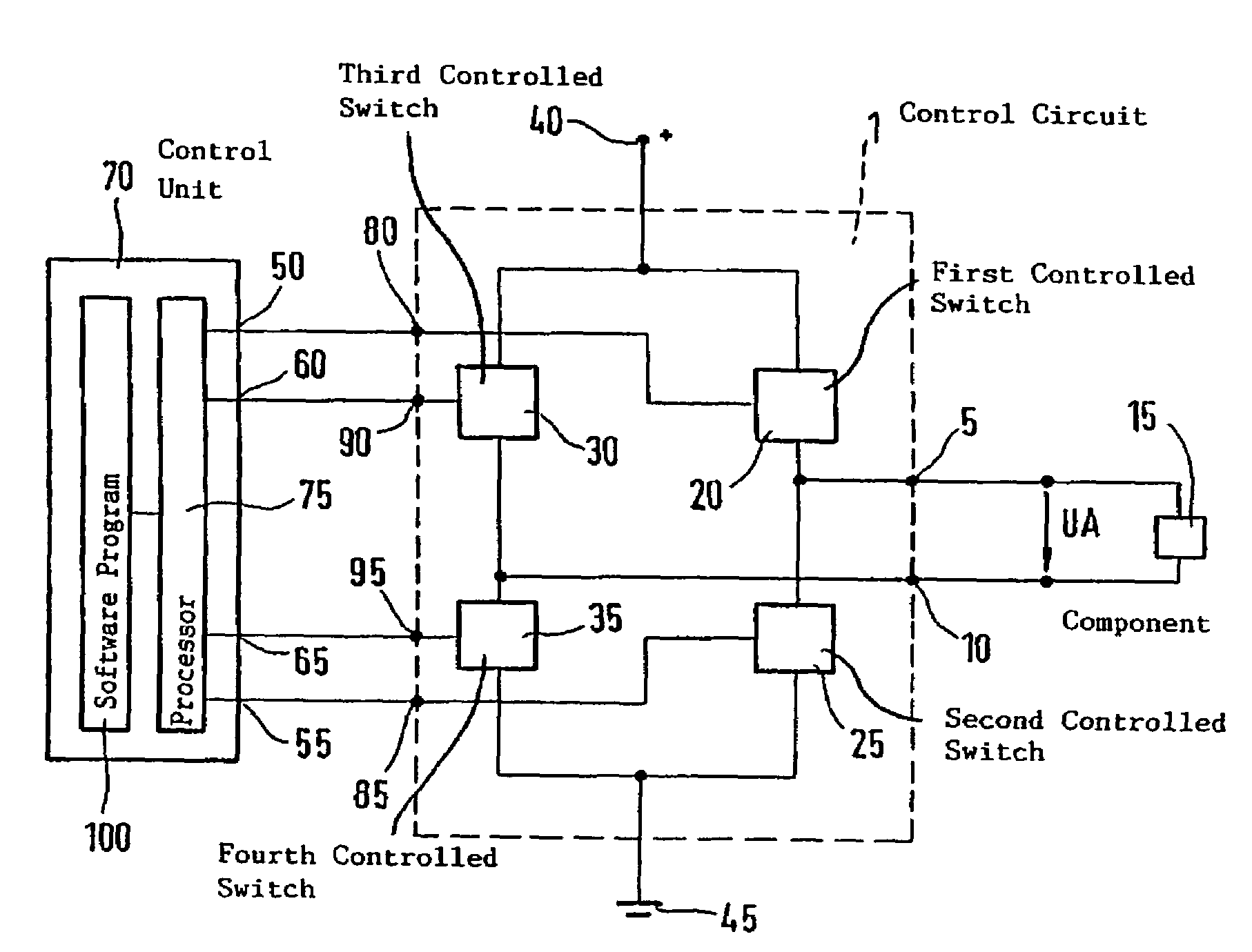
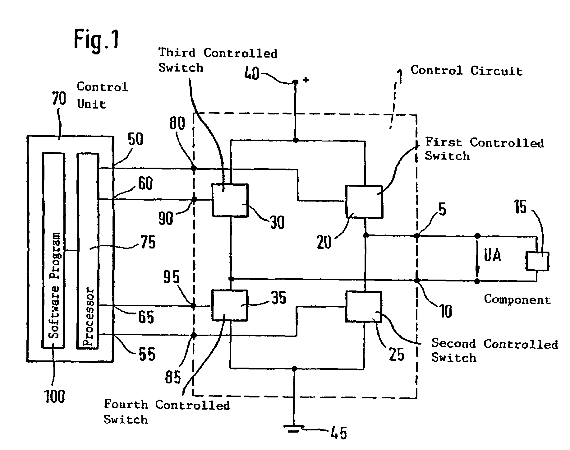
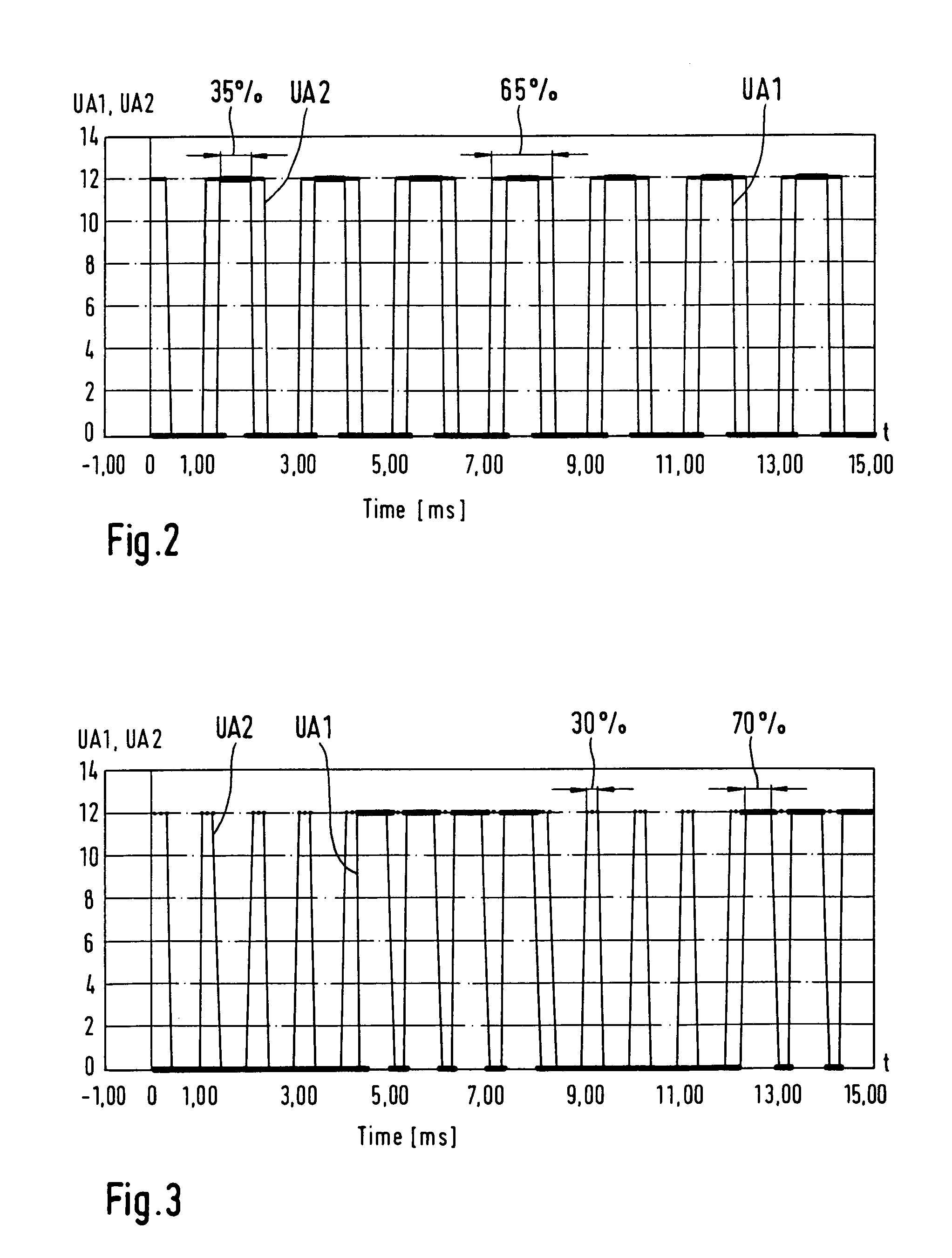
[0022]The first output signal UA1 results at the first input 5 with the frequency 500 Hz and the drive contact rate of 35% in correspondence to the drive signal at the first input (80, 85). In correspondence to the drive signals at the second input (90, 95), the second output UA2 having the frequency of 500 Hz and the drive contact rate of 65% results at the second output 10. The two output signals (UA1, UA2) also have the coincident symmetry axes described for the input signals. The two output signals (UA1, UA2) are shown in the signal diagram of FIG. 2. If one forms the difference (UA2−UA1) from the two periodic output signals (UA1, UA2), then the drive voltage UA (which is shown in FIG. 4) results at a frequency of 1 kHz and the drive contact rate of 30%. With this first embodiment of the invention, both controllable switch means (20, 25; 30, 35) are alternately switched so that the generated power loss and therefore the heat is distributed over both switchable switch means (20, ...

second embodiment

[0023] the processor 75 is so set that it generates a drive signal with a drive contact rate of 70% and a frequency of 1 kHz at the first input (80, 85). This drive signal for the first input (80, 85) is generated by the processor 75 in a first operating mode. In this first operating mode, the second input (90, 95) is continuously held at “high”. In this way, the first output signal UA1 having a drive contact rate of 70% results at the first input 5 corresponding to the drive signal at the first input (80, 85) while, in contrast, the second output signal UA2 at the second output 10 lies continuously at “high”. In the difference (UA2−UA1) of the two output signals (UA1, UA2), there results again the pregiven drive voltage UA having a drive contact rate of 30% and a frequency of 1 kHz. In a second operating mode, the processor 75 generates a drive signal at the second input (90, 95) which has a drive contact rate of 30% with a frequency of 1 kHz. At the same time, the first input (80,...


PUM


Abstract

A method and a control unit for driving a control circuit (1) are suggested which make possible an improved distribution of the generated power loss. A component (15), especially of a motor vehicle, is driven via at least two outputs (5, 10) of the control circuit (1). Each output (5, 10) is connected pairwise to one of several potentials (40, 45) via controllable switch means (20, 25; 30, 35) and a drive voltage (UA) is formed for the component (15) from a difference between the potentials at the two outputs (5, 10). A pregiven clocked course of the drive voltage (UA) is adjusted by switching more than one of the controllable switch devices (20, 25; 30, 35).

Description

BACKGROUND OF THE INVENTION[0001]Control circuits are already known which include two outputs for driving a component, especially of a motor vehicle. The component can, for example, be configured as the following: a throttle flap actuator; an exhaust-gas control actuator; a charge-movement actuator; a circulating air actuator in compressor motors; a variable valve drive adjustor or the like. Each output of the control circuit is selectably connectable to an operating voltage potential or a reference potential via a controllable switching means. A drive voltage for the component is formed from a difference between the potentials at the two outputs. A control circuit of this kind can, for example, be realized by a so-called H-bridge circuit as is known, for example, from Motorola as automotive H-bridge driver MC 33186. To drive the control circuit, usually two input signals are used, namely, a pulsewidth-modulated signal for a first input of the control circuit and a constant operatio...

Claims


Application Information

Patent Timeline
Patent Type & Authority Patents(United States)
IPC IPC(8): H01H3/26B60R16/02H02P7/00H02P7/29
CPCH02P7/0044H02P7/04
Inventor GROSSMANN, ALEXBAUMANN, TORSTEN
Owner ROBERT BOSCH GMBH
Why Eureka
Try Eureka