Sample hold circuit and multiplying D/A converter having the same

a technology of multiplying d/a converter and sample hold circuit, which is applied in the direction of pulse technique, electric analogue stores, instruments, etc., can solve the problems of error introduced into the output of a/d converter, and achieve the effect of accurate holding and suitable gain and slew ra

Active Publication Date: 2008-07-08
DENSO CORP
View PDF16 Cites 32 Cited by
  • Summary
  • Abstract
  • Description
  • Claims
  • Application Information

AI Technical Summary

Benefits of technology

[0011]The sampling hold circuit is configured such that a total capacitance of the first and second capacitors to which an input voltage is applied in the sampling phase is equal to that of the first and second capacitors to which the input voltage is applied in the holding phase. Therefore, an input voltage applied to the op-amp is independent of the input voltage in the sampling phase. Thus, the input voltage applied to the op-amp in the holding phase can be kept constant at a predetermined common mode input voltage regardless of the magnitude of input voltage in the sampling phase. Thus, the op-amp can work with a suitable gain and slew rate.
[0012]Further, the sampling hold circuit is configured such that a total capacitance of the first capacitors to which the input voltage is applied in the holding phase is equal to that of the second capacitors to which the input voltage is applied in the holding phase. Therefore, the sampled voltage can be accurately held even when the input voltage changes in the holding phase.

Problems solved by technology

As a result, an error is introduced into the output of the A / D converter.

Method used


Image

  • Sample hold circuit and multiplying D/A converter having the same
  • Sample hold circuit and multiplying D/A converter having the same
  • Sample hold circuit and multiplying D/A converter having the same

Examples


first embodiment

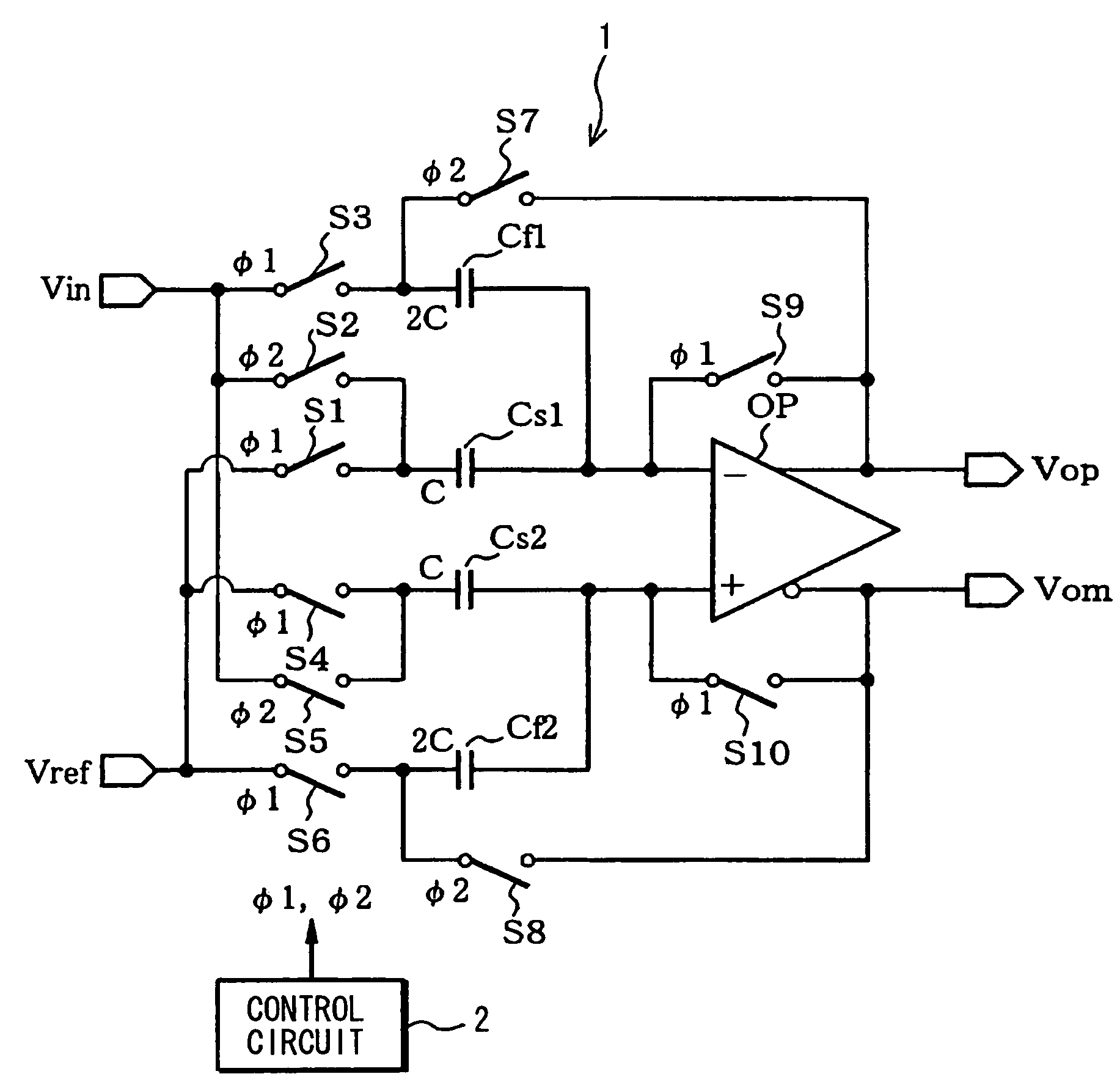
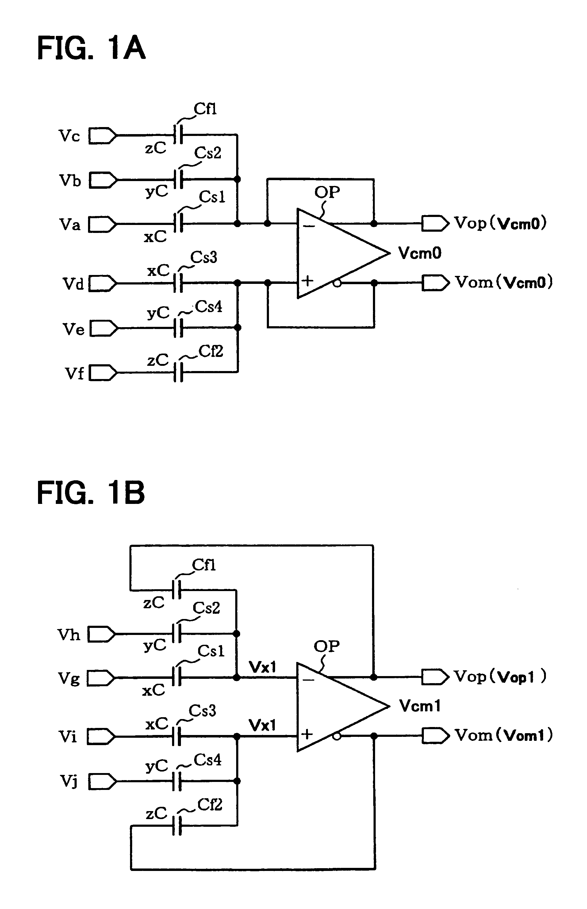
[0028]Referring to FIGS. 1A and 1B, a sample hold circuit according to the first embodiment includes an operational amplifier (op-amp) OP and six capacitors, three of which are provided on an inverting side of the op-amp OP and three of which are provided on a non-inverting side. One of the three capacitors provided on the inverting side is used as a feedback capacitor. Likewise, one of the three capacitors provided on the non-inverting side is used as the feedback capacitor.

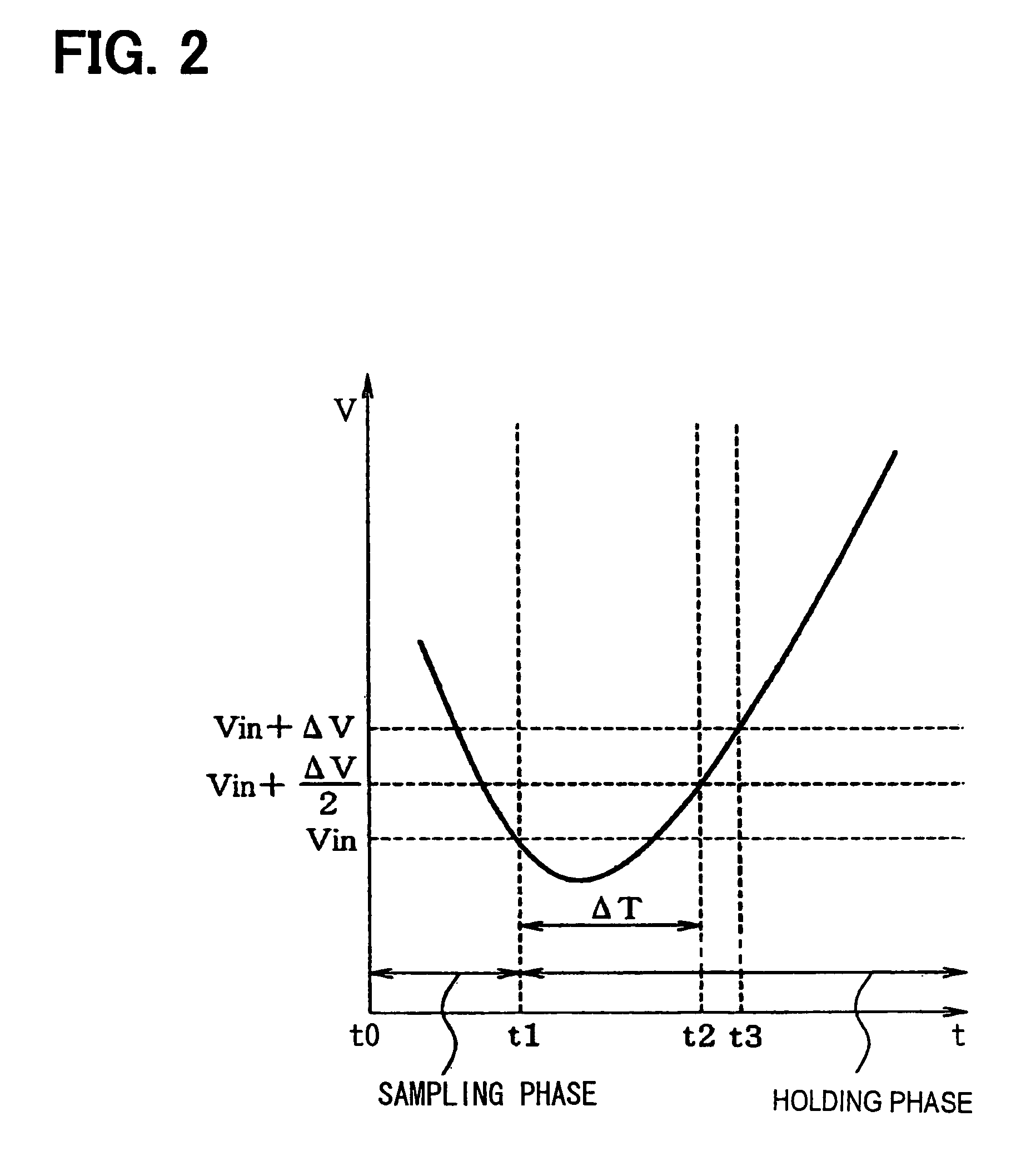
[0029]The sample-hold circuit shown in FIGS. 1A and 1B implements features 1A to 1D listed below. Vin is an input voltage applied to the sample-hold circuit in a sampling phase and Vin+ΔV is an input voltage applied to the sample-hold circuit in a holding phase.

[0030](Feature 1A)

[0031]The sample-hold circuit converts a single ended input to a differential output.

[0032](Feature 1B)

[0033]The input voltage Vin is applied to at least one of the capacitors in a sampling phase and the input voltage Vin+ΔV is applied t...

second embodiment

[0104]A sample hold circuit according to the second embodiment is similar in configuration to the sample hold circuit according to first embodiment shown in FIGS. 1A and 1B. The first and second embodiments are different in the capacitance of the capacitors and in the manner in which the input voltages Vin, Vin+A are applied.

[0105]The sample-hold circuit of the second embodiment implements features 2A-2D listed below. The features 1A, 1B, 1D are the same as the features 2A, 2B, 2D, respectively.

[0106](Feature 2A)

[0107]The sample-hold circuit converts the single ended input to the differential output.

[0108](Feature 2B)

[0109]The input voltage Vin is applied to at least one of the capacitors in the sampling phase and the input voltage Vin+ΔV is applied to one of the capacitors in the holding phase.

[0110](Feature 2C)

[0111]The sample-hold circuit amplifies the input voltage Vin with the predetermined gain and holds the amplified input voltage. The held voltage (differential output voltag...

third embodiment

[0156]Referring to FIGS. 3A and 3B, a sample hold circuit according to the third embodiment includes the operational amplifier (op-amp) OP and eight capacitors, four of which are provided on the inverting side of the op-amp OP and four of which are provided on the non-inverting side.

[0157]The sample hold circuit according to the third embodiment implements the features 1A-1D described in the first embodiment or the features 2A-2D described in the second embodiment.

[0158]As shown in FIGS. 3A and 3B, the sample hold circuit includes four capacitors Cs1, Cs2, Cf1, Cf2, each of which has one end connected to the inverting input of the op-amp OP and four capacitors Cs3, Cs4, Cf3, Cf4, each of which has one end connected to the non-inverting input of the op-amp OP.

[0159]The capacitors Cs1, Cs3 are paired as the first capacitor pair and each of the capacitors Cs1, Cs3 has a capacitance of xC, where x represents the positive integer and C represents the unit capacitance. The capacitors Cs2,...


PUM


Abstract

A sample hold circuit includes an op-amp, first capacitors provided on an inverting side of the op-amp and second capacitors provided on a non-inverting side. The sample hold circuit is configured such that a total capacitance of the first and second capacitors to which an input voltage is applied in a sampling phase is equal to that of the first and second capacitors to which the input voltage is applied in a holding phase, a total capacitance of the first capacitors to which the input voltage is applied in the holding phase is equal to that of the second capacitors to which the input voltage is applied in the holding phase, and a total capacitance of the first capacitors to which the input voltage is applied in the sampling phase is different from that of the second capacitors to which the input voltage is applied in the sampling phase.

Description

CROSS REFERENCE TO RELATED APPLICATION[0001]This application is based on and incorporates herein by reference Japanese Patent Applications No. 2005-323549 filed on Nov. 8, 2005 and No. 2006-203205 filed on Jul. 26, 2006.FIELD OF THE INVENTION[0002]The present invention relates to a sample hold circuit and a multiplying D / A converter having the sample hold circuit.BACKGROUND OF THE INVENTION[0003]As disclosed in JP-2005-39529A and JP-2003-298418A, a pipeline analog to digital converter (ADC) includes a sub-ADC, a sub-digital to analog converter (DAC), an adder circuit, and an operational amplifier (op-amp).[0004]The sub-ADC is a 1.5-bit ADC and converts an analog input voltage to an A / D conversion value consisting of three binary numbers. The sub-DAC outputs +Vref / 2, 0, or, −Vref / 2, in accordance with the A / D conversion value. The adder circuit adds the analog input voltage and the output of the sub-DAC. The op-amp amplifies the output of the adder circuit with a predetermined gain (...

Claims


Application Information

Patent Timeline
Patent Type & Authority Patents(United States)
IPC IPC(8): H03K5/00
CPCG11C27/026H03M1/0607H03M1/164H03M1/0695H03M1/162H03M1/0682
Inventor MAKIHARA, TETSUYA
Owner DENSO CORP
Why Eureka
Try Eureka