Orthomode transducer

a transducer and orthomode technology, applied in the direction of coupling devices, waveguide type devices, basic electric elements, etc., can solve the problems of insufficient isolation, ineffectiveness, and insufficient omts of today, and achieve low vswr, high mode purity, and high power handling capability.

Inactive Publication Date: 2008-07-08
X ETHER
View PDF22 Cites 22 Cited by
  • Summary
  • Abstract
  • Description
  • Claims
  • Application Information

AI Technical Summary

Benefits of technology

[0017]An advantage of the present invention is that it provides an inherently compact and thin waveguide orthomode transducer (OMT).
[0018]Another advantage of the invention is that the OMT may be embodied to have high power handling capability, or may be embodied to trade power handling capability for additional compactness and thickness reduction.
[0019]Another advantage of the invention is that the resulting OMT has high mode purity over a broad bandwidth, provides low VSWR, and exhibits high isolation between ports.
[0020]And another advantage of the invention is that the OMT is easy to manufacture.
[0021]These and other objects and advantages of the present invention will become clear to those skilled in the art in view of the description of the best presently known mode of carrying out the invention and the industrial applicability of the preferred embodiment as described herein and as illustrated in the figures of the drawings.

Problems solved by technology

Unfortunately, most OMTs today are not fully satisfactory.
For example, they may not be effective in preventing the generation of undesirable higher order modes, or they may not provide sufficiently high isolation between ports, or they may be difficult to manufacture and thus relatively expensive, or they may be unduly bulky and too thick for many important applications.
NAVARRINI & PLAMBECK teach fabricating their device from four machined bocks that are bolted together, thus being especially challenging to manufacture economically.
However, this excessive reduction of waveguide height compromises power handling capability, and the passing over itself increases thickness of the overall device.
In summary turnstile junction-based OMTs generally remain bulky and thick, or else require accepting undesirable performance compromises.

Method used


Image

  • Orthomode transducer
  • Orthomode transducer
  • Orthomode transducer

Examples


Embodiment Construction

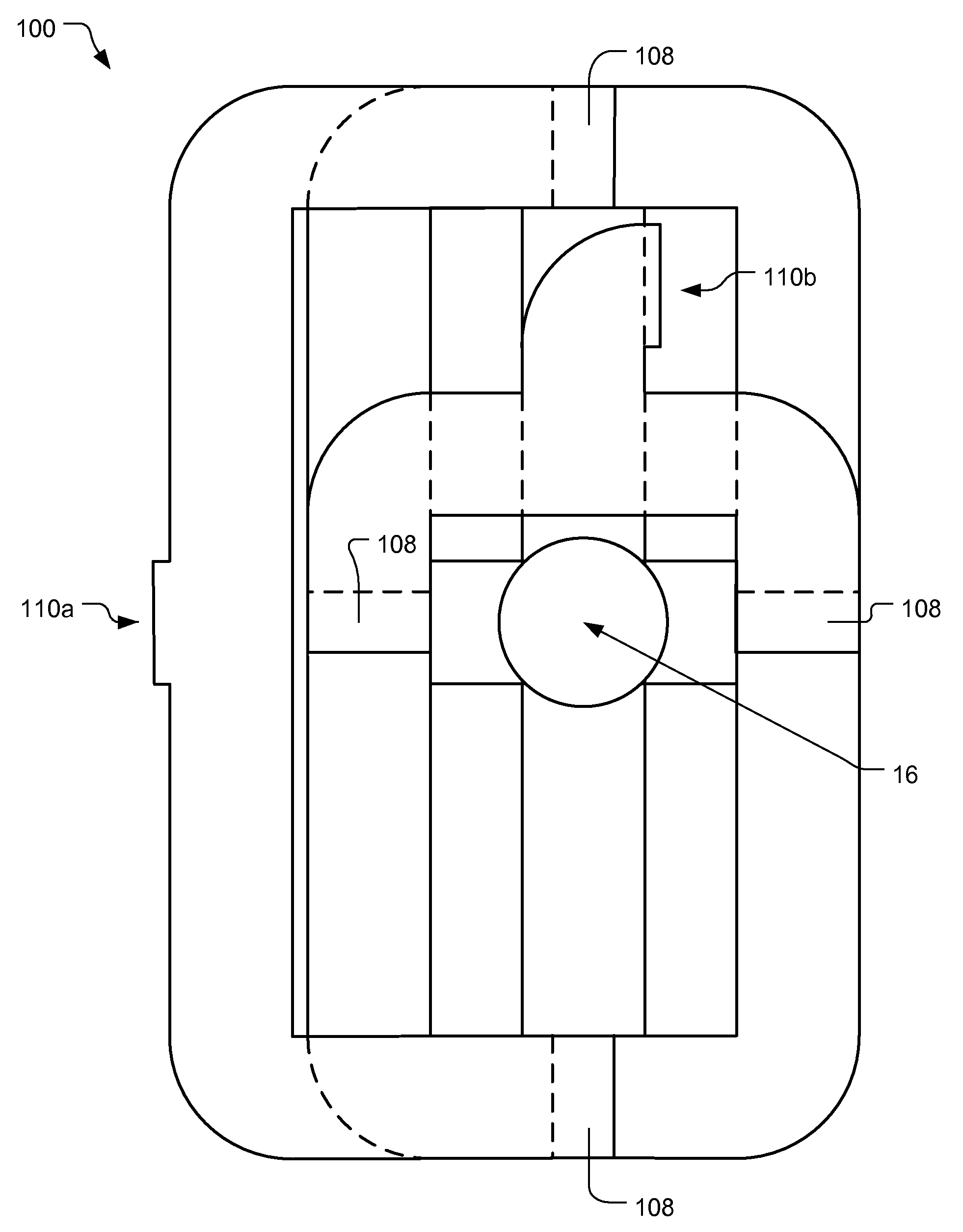
[0029]A preferred embodiment of the present invention is a waveguide orthomode transducer (OMT). As illustrated in the various drawings herein, and particularly in the view of FIG. 4a, preferred embodiments of the invention are depicted by the general reference character 100.

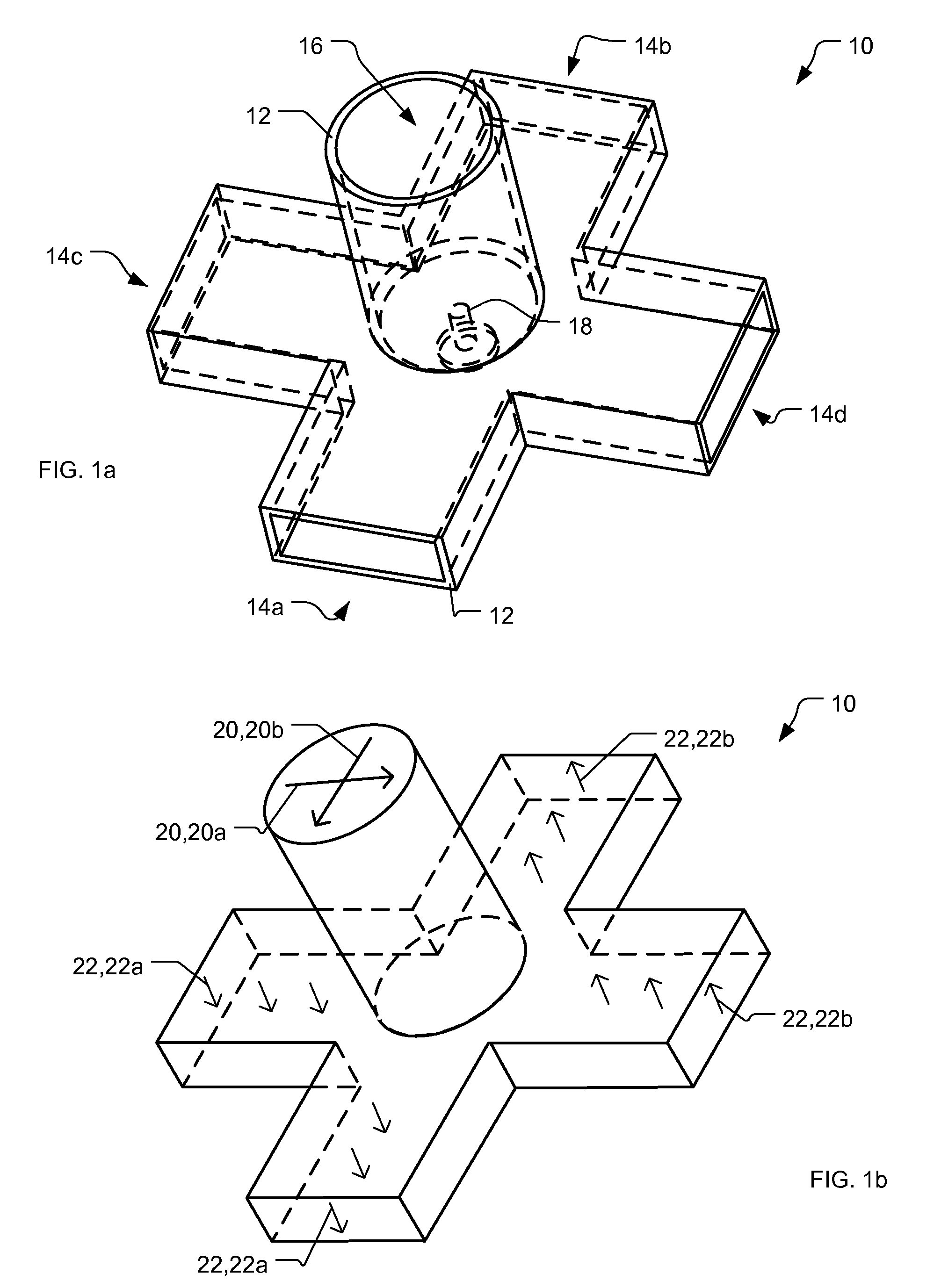
[0030]Briefly, the inventive OMT combines connecting waveguides as needed, a turnstile junction, and four hybrid tees functioning as both H-plane and E-plane power dividers / combiners on a first layer, and connecting waveguides as needed and two H-plane T-junctions or hybrid tees with terminated E-ports functioning as H-plane power dividers / combiners on a second layer. A waveguide port is provided on the first layer and two polarization ports are provided on and oriented coplanar with the second layer, thus making the OMT notably compact. Furthermore, since there is no interference issue for the elements to avoid, they can be optimally dimensioned, and thus allow the OMT to achieve close to theoretical maximum pe...


PUM


Abstract

A waveguide orthomode transducer. In a first layer a turnstile junction having a main waveguide and four waveguide ports, and four hybrid tees each have an e-port, two opposed side-ports, and an h-port. The hybrid tees are ring-arranged around the turnstile junction so the waveguide ports each communicate with one h-port, so adjacent hybrid tees inter communicate with their respective side-ports, and so the e-ports form two sets of opposed e-ports. In a second layer two h-plane power dividers / combiners each have an axial-port and two opposed side-ports. The h-plane power dividers / combiners are arranged so their respective side-ports communicate with different ones of the two sets of opposed e-ports and so their axial-ports are polarization ports. This permits a single signal with two fundamental orthogonally polarized modes to enter the main waveguide and exit separated at the polarization ports vice versa.

Description

TECHNICAL FIELD[0001]The present invention relates generally to wave transmission lines and networks, and more particularly to such that include a hybrid-type network.BACKGROUND ART[0002]A waveguide orthomode transducer (OMT) is a radio frequency (RF) device often used to combine or separate orthogonally polarized signals, thus providing polarization-discrimination. OMTs also have important utility as polarization diplexers.[0003]Unfortunately, most OMTs today are not fully satisfactory. For example, they may not be effective in preventing the generation of undesirable higher order modes, or they may not provide sufficiently high isolation between ports, or they may be difficult to manufacture and thus relatively expensive, or they may be unduly bulky and too thick for many important applications.[0004]There are various types of OMTs, and one type based on a turnstile waveguide junction is of interest here because it can overcome some of the just noted shortcomings. Turnstile juncti...

Claims


Application Information

Patent Timeline
Patent Type & Authority Patents(United States)
IPC IPC(8): H01P5/12H01P1/161H01P5/22
CPCH01P1/161
Inventor TAVASSOLI HOZOURI, BEHZAD
Owner X ETHER
Why Eureka
Try Eureka