Smart repair patch and associated method

a patch and repair technology, applied in the field of smart patches, to achieve the effect of reducing cost and accelerating inspection of composite and metallic structures

Active Publication Date: 2008-07-15
THE BOEING CO
View PDF27 Cites 80 Cited by
  • Summary
  • Abstract
  • Description
  • Claims
  • Application Information

AI Technical Summary

Benefits of technology

[0008]Embodiments of the invention address the above needs and achieve other advantages by providing a system to inspect a repair patch applied to a structure for defects. In particular, the system is capable of inspecting a repair patch that has been attached to a structure. The system incorporates a sheet of material having several sensors secured thereon. A mechanism is used to generate stress waves within and along a surface of the sheet of material. The sensors communicate with a data acquisition system to generate information that identifies defects within the sheet of material. Employing an impact-echo method, for example, allows the inspection system to inspect composite and metallic structures more rapidly and at a lower cost than conventional inspection techniques.

Problems solved by technology

In addition, the data acquisition system may generate information indicative of a defect in the sheet of material based on the data detected by the sensors.

Method used


Image

  • Smart repair patch and associated method
  • Smart repair patch and associated method
  • Smart repair patch and associated method

Examples


Embodiment Construction

[0019]The present invention now will be described more fully hereinafter with reference to the accompanying drawings, in which some, but not all embodiments of the invention are shown. Indeed, the invention may be embodied in many different forms and should not be construed as limited to the embodiments set forth herein; rather, these embodiments are provided so that this disclosure will satisfy applicable legal requirements. Like numbers refer to like elements throughout.

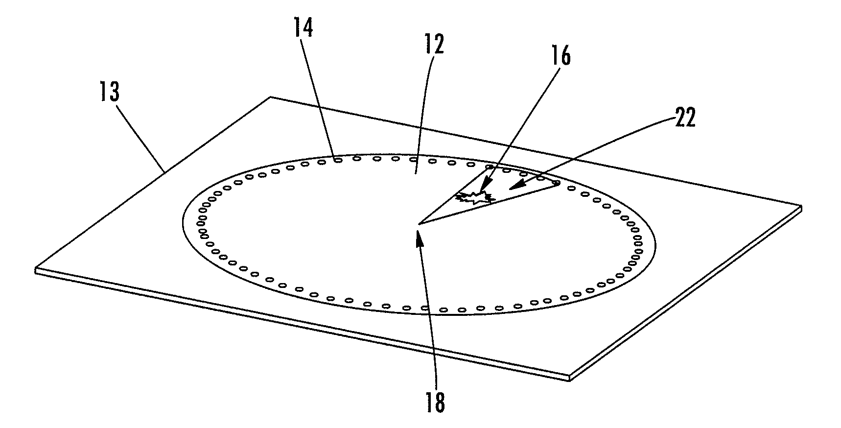
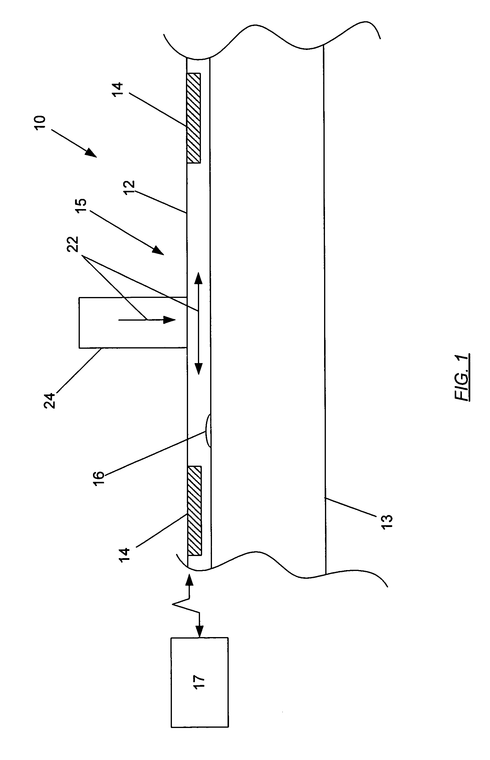
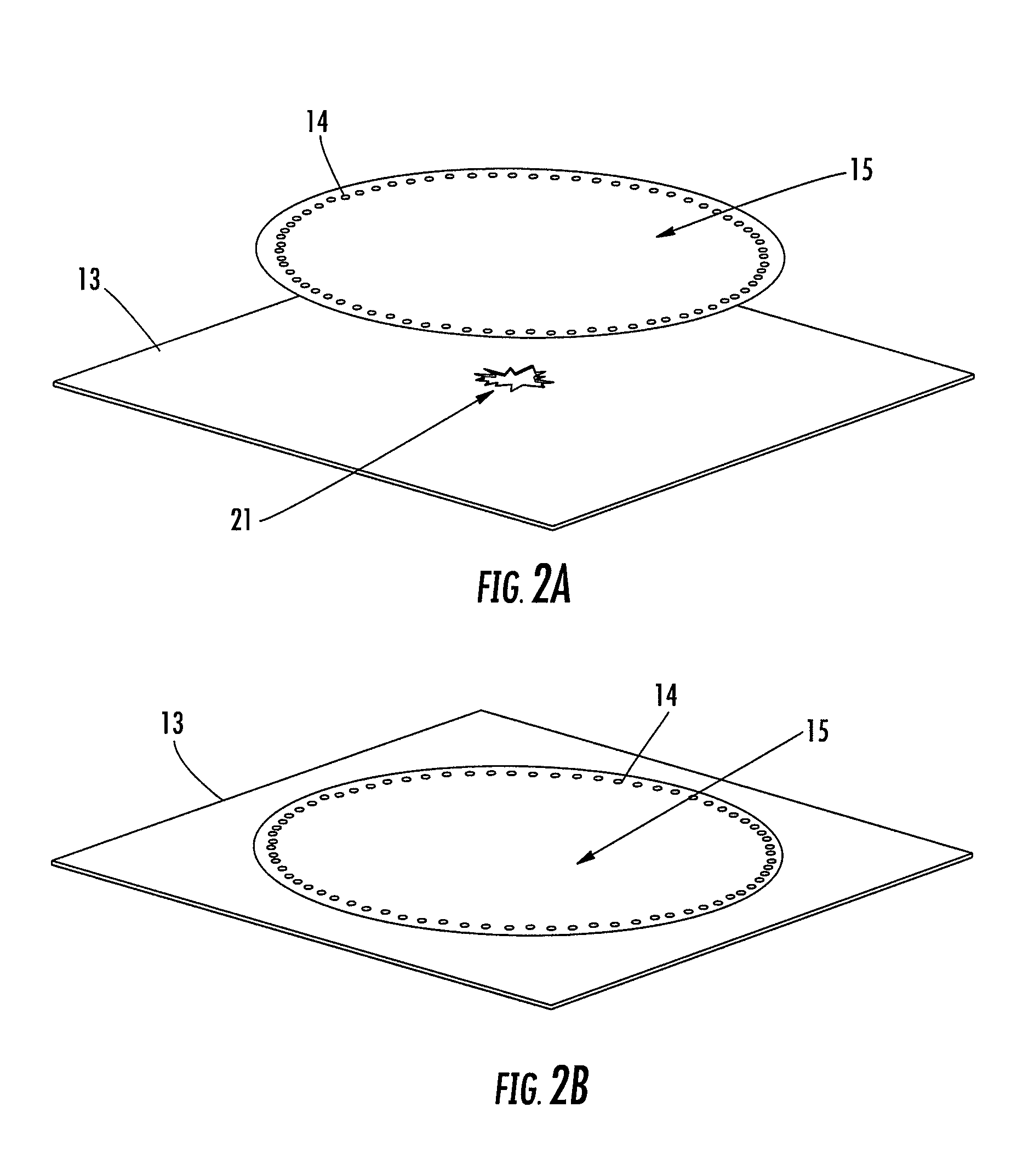
[0020]Referring now to the drawings and, in particular to FIGS. 1 and 2A-2B, there is shown an inspection system 10. The inspection system 10 includes a repair patch 15 that is attached to a structure 13 for repairing a defect in a structure. The repair patch could be employed to repair or detect any number of defects 21 within or along a surface of the structure 13 such as cracks, disbonds, discontinuities, voids, or porosity, which could adversely affect the performance of the structure (see FIGS. 2A-2B). The rep...


PUM

PropertyMeasurementUnit
defectsaaaaaaaaaa
stressaaaaaaaaaa
adhesionaaaaaaaaaa

Abstract

A system and method for identifying defects in a repair patch applied to a structure are provided. The system includes a sheet of material configured to be attached to the structure, and a mechanism operable to generate stress waves within and along the sheet of material. The system also includes a plurality of non-destructive sensors carried by the sheet of material. Each sensor is capable of detecting the stress waves. The system further includes a data acquisition system capable of communicating with the sensors such that the data acquisition system is also capable of generating information indicative of at least a portion of the sheet of material based on the data detected by the sensors.

Description

BACKGROUND OF THE INVENTION[0001]1) Field of the Invention[0002]The present invention relates to smart patches and, more particularly, to a smart repair patch for monitoring the integrity of the repair patch.[0003]2) Description of Related Art[0004]Materials and structures employed in the aerospace industry and elsewhere may periodically require repair for in-service damage. Rapid inspection and repair of aircraft or ground vehicles are important for military and commercial applications in order to decrease down time. Temporary patch repairs of a metallic or composite structure are sometimes utilized to enable continuing use of the vehicle, such as an aircraft, until a permanent repair may be made. Temporary patches cost less than permanent repairs and can be installed very rapidly. In addition, temporary patches reduce down time and provide flexibility for utilizing the best schedule and cost options available.[0005]However, confidence in the quality of the temporary repairs has de...

Claims


Application Information

Patent Timeline
Patent Type & Authority Patents(United States)
IPC IPC(8): G01N29/04G01N3/00
CPCG01M5/0033G01N29/045G01N2203/0688G01N2203/0623G01N2203/001
Inventor GRIESS, KENNETH H.GEORGESON, GARY E.
Owner THE BOEING CO
Why Eureka
Try Eureka