Compression ignition initiation device and internal combustion engine using same

a technology of compression ignition and ignition initiation device, which is applied in the direction of machines/engines, output power, electric control, etc., can solve the problems of limiting the leanness of the fuel and air mixture, the inability of many hcci engines to operate across a portion of their theoretical load range, and the rapid heat release of conventional engines

Active Publication Date: 2008-07-15
CATERPILLAR INC
View PDF31 Cites 12 Cited by
  • Summary
  • Abstract
  • Description
  • Claims
  • Application Information

AI Technical Summary

Problems solved by technology

The relatively greater amount of time available for the fuel and air to mix tends to result in a more rapid heat release than in conventional engines.
In the context of compression ignition engines in particular, there is a limit as to how lean the fuel and air mixture may be, while still reliably autoigniting.
Moreover, many HCCI engines are only able to operate across a portion of their theoretical load range, due at least in part to the relatively high pressure spikes which can result from the rapid, fairly uniform ignition of the fuel and air mixture throughout the cylinder.
In particular, the relatively larger amounts of combusting fuel necessary to accommodate larger loads can simply create more pressure than the engine components can withstand.
A further challenge to HCCI engine designers relates to the difficulty in autoigniting a fuel and air mixture at a desired time.
HCCI engines lack a natural control mechanism for ignition timing, such as the spark timing and fuel injection timing of spark ignited and conventional compression ignition engines, respectively.
Moreover, ignition timing in HCCI tends to be sensitive to speed and load changes, combustion characteristics of previous engine cycles, and the specific fuel formulation and decomposition properties.
As much of the potential of HCCI strategies for improved emissions quality relies upon igniting a lean mixture at a prescribed time such as at or near top dead center, the technology has yet to fulfill certain of its promises.

Method used


Image

  • Compression ignition initiation device and internal combustion engine using same
  • Compression ignition initiation device and internal combustion engine using same
  • Compression ignition initiation device and internal combustion engine using same

Examples


Embodiment Construction

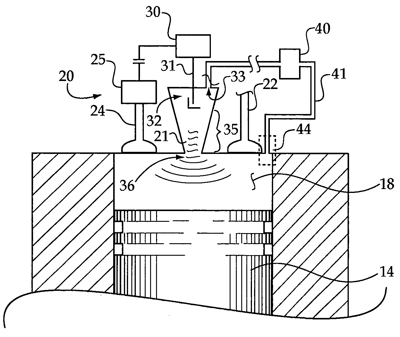
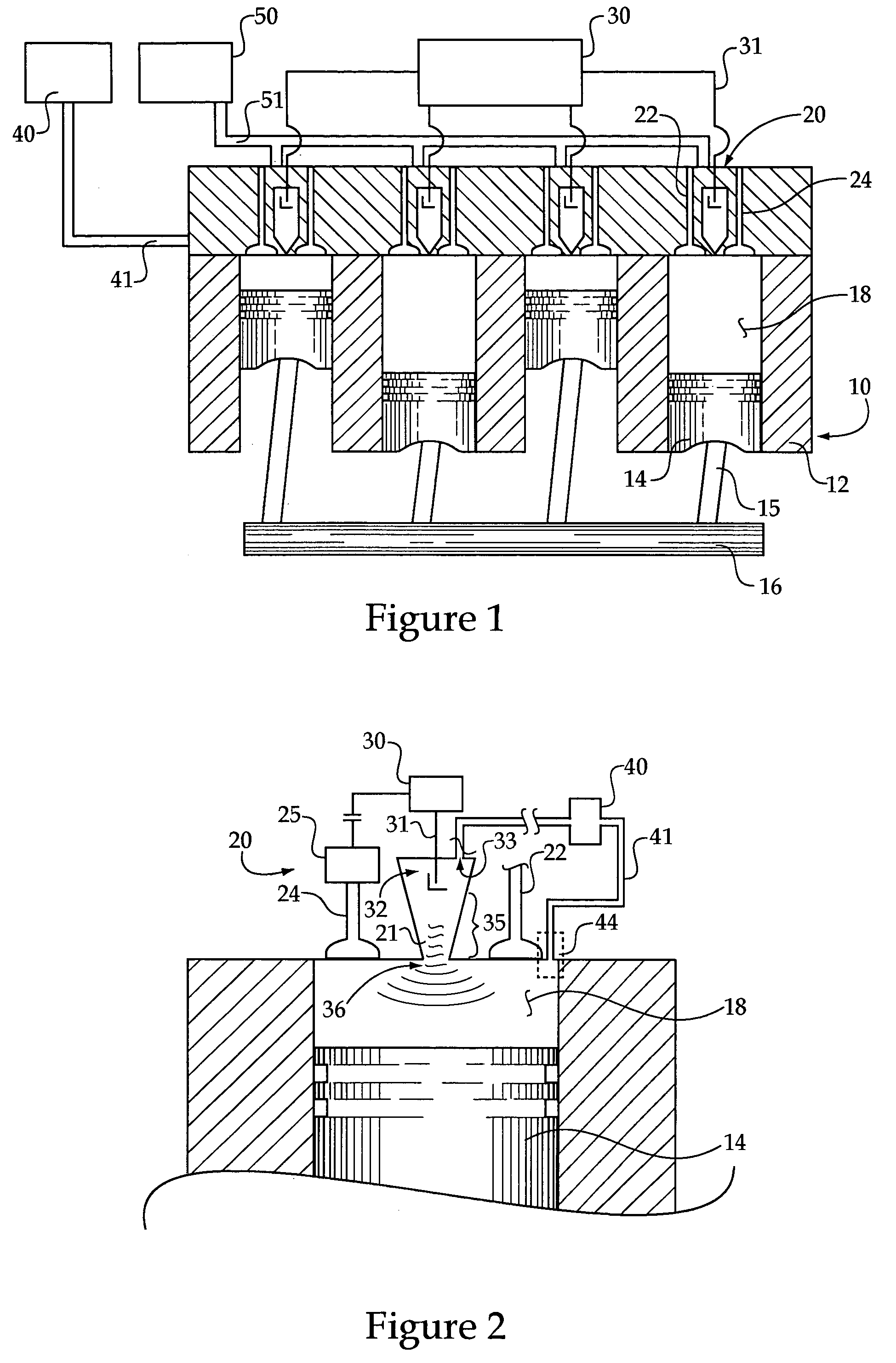
[0015]Referring to FIG. 1, there is shown a partially sectioned side view of an engine 10 according to the present disclosure. Engine 10 includes a housing 12 having at least one cylinder 18, for example, a plurality of cylinders disposed therein. A piston 14 is moveably positioned within each cylinder 18, and connects with a crankshaft 16 via a rod 15. A first gas exchange valve 22, and a second gas exchange valve 24 are typically disposed in housing 12, and operable to control exhaust and intake of each respective cylinder 18 in a conventional manner. By controlling the opening / closing timings of valves 22 and 24, the compression ratio within each cylinder 18 may also be varied, as is well known in the art.

[0016]A fuel supply 40 connects with housing 12 via a primary fuel supply line 41. A fuel reformer 50, described herein, may also be connected with fuel supply 40 and with engine housing 12 via a secondary fuel supply line 51. A compression ignition initiation device 20 will typ...


PUM


Abstract

An internal combustion engine having a compression ignition initiation device is provided. The compression ignition initiation device includes a body defining a chamber and an outlet from the chamber. The device further includes means, within the chamber, for generating a combustion initiating shock front from the outlet. A method is provided, including compressing a mixture of fuel and air in an internal combustion engine cylinder to a point less than a compression ignition threshold, and initiating ignition of the mixture by subjecting it to a shock front.

Description

TECHNICAL FIELD[0001]The present disclosure relates generally to internal combustion engines that ignite a premixed charge of fuel and air, and relates more particularly to a compression ignition initiation device for use in such an internal combustion engine.BACKGROUND[0002]Internal combustion engine technology continues to advance. Improvements in reliability, emissions quality and fuel efficiency are revealed on an almost daily basis. Over the last several decades, particular attention has been paid to technologies capable of reducing the levels of certain emissions in exhaust from internal combustion engines. One class of emissions compounds of special interest is known in the art as “NOx”, and includes various nitrogen-oxygen compounds. Various schemes have been proposed over the years for operating internal combustion engines such that the relative quantities of NOx in the engine exhaust are reduced. One approach showing much promise involves running the engine relatively lean...

Claims


Application Information

Patent Timeline
Patent Type & Authority Patents(United States)
IPC IPC(8): F02B19/18
CPCF02B1/12F02B9/04F02B19/108F02B19/12F02D13/0269F02D15/04F02D19/0671F02D41/3041F02D19/0642F02D19/081Y02T10/125Y02T10/36Y02T10/142Y02T10/12Y02T10/30
Inventor FIVELAND, SCOTT B.
Owner CATERPILLAR INC
Why Eureka
Try Eureka