
Wire-feeding device for a wire-processing machine

a wire-feeding device and wire-processing machine technology, which is applied in the direction of feeding apparatus, automatic control devices, precision positioning equipment, etc., can solve the problems of wire loops and/or wire knots, wire snapping of wires with very fine wires, and inability to meet the stepwise requirement of wires of the wire-processing machine. , to achieve the effect of simple and inexpensive means and little expens

Active Publication Date: 2008-07-15
KOMAX HOLDING
View PDF22 Cites 6 Cited by
  • Summary
  • Abstract
  • Description
  • Claims
  • Application Information

AI Technical Summary

Benefits of technology

The present invention provides a remedy for the disadvantages of existing wire-processing machines by creating an inexpensive device for feeding wires to wire-processing machines. The wire-processing machine transfers wires at high speed and acceleration. However, the wire needs to be removed from its source in a controlled and efficient manner. The present invention solves this problem by providing a feeding device that allows for smooth removal of wires from drums or reels without causing damage or snapping. The feeding device includes a wire-path with a free-hanging wire-loop that prevents the wire from getting tangled or kinked. The wire-feeder prevents static charging of the wire and is space-saving. Overall, the present invention provides a cost-effective solution for wire processing.

Problems solved by technology

The stepwise requirement for wire of the wire-processing machine cannot be readily met out of a drum or off a reel.
For example, jerky removal of the wire from the drum would result in wire loops and / or wire knots.
Jerky removal of the wire from the reel would cause snapping of the wire with very fine wires.
However, reel diameters cannot be made smaller indefinitely since for processing the wire-ends and for storing the wires straight and kink-free wires are essential.
Thus the overall length of the machine is increased only insignificantly.

Method used


Image

  • Wire-feeding device for a wire-processing machine
  • Wire-feeding device for a wire-processing machine
  • Wire-feeding device for a wire-processing machine

Examples


Embodiment Construction

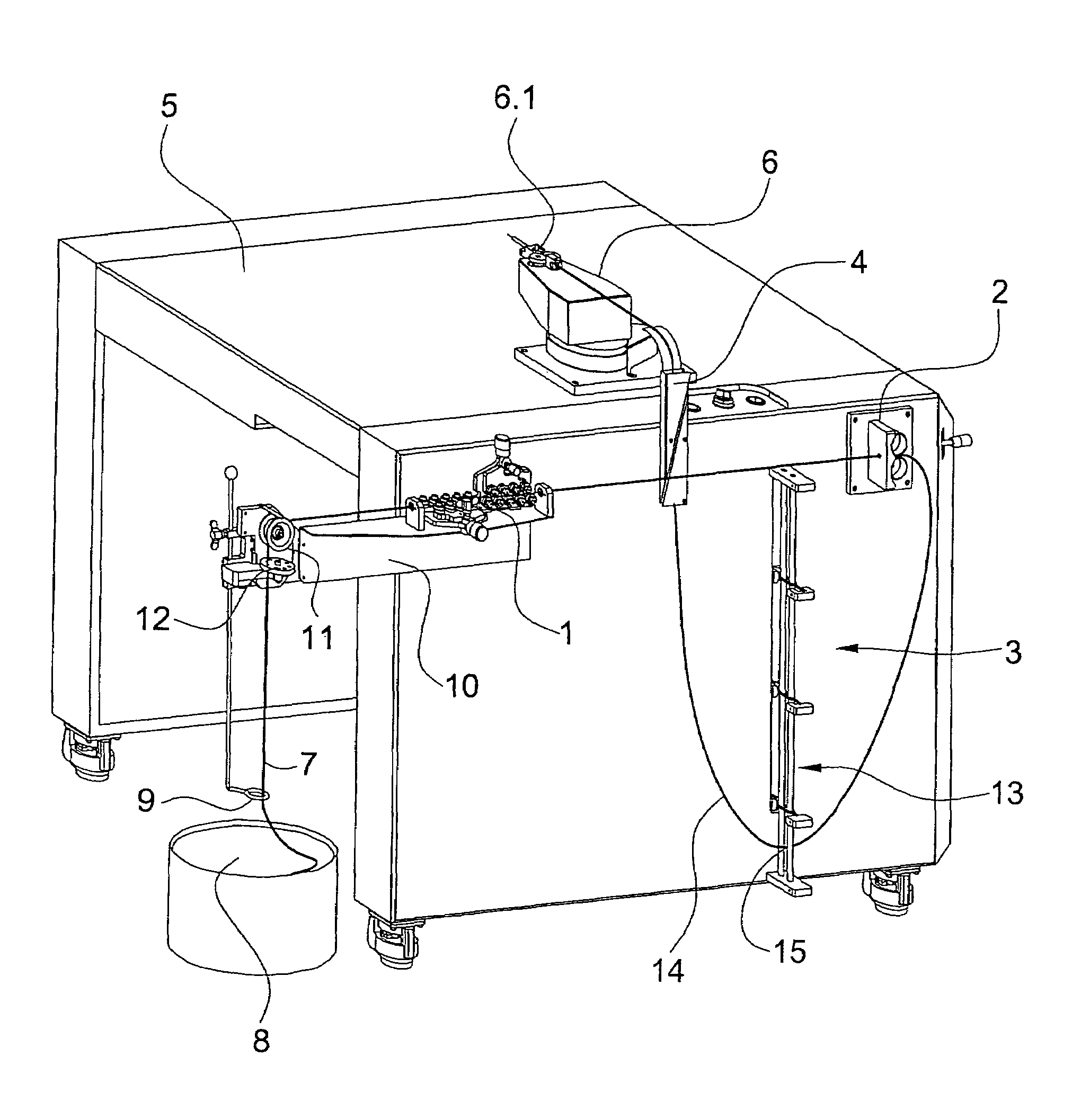
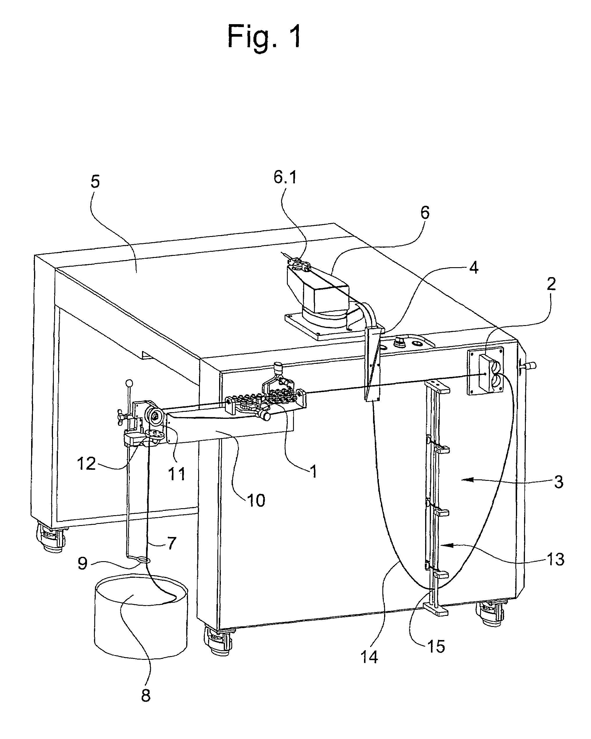
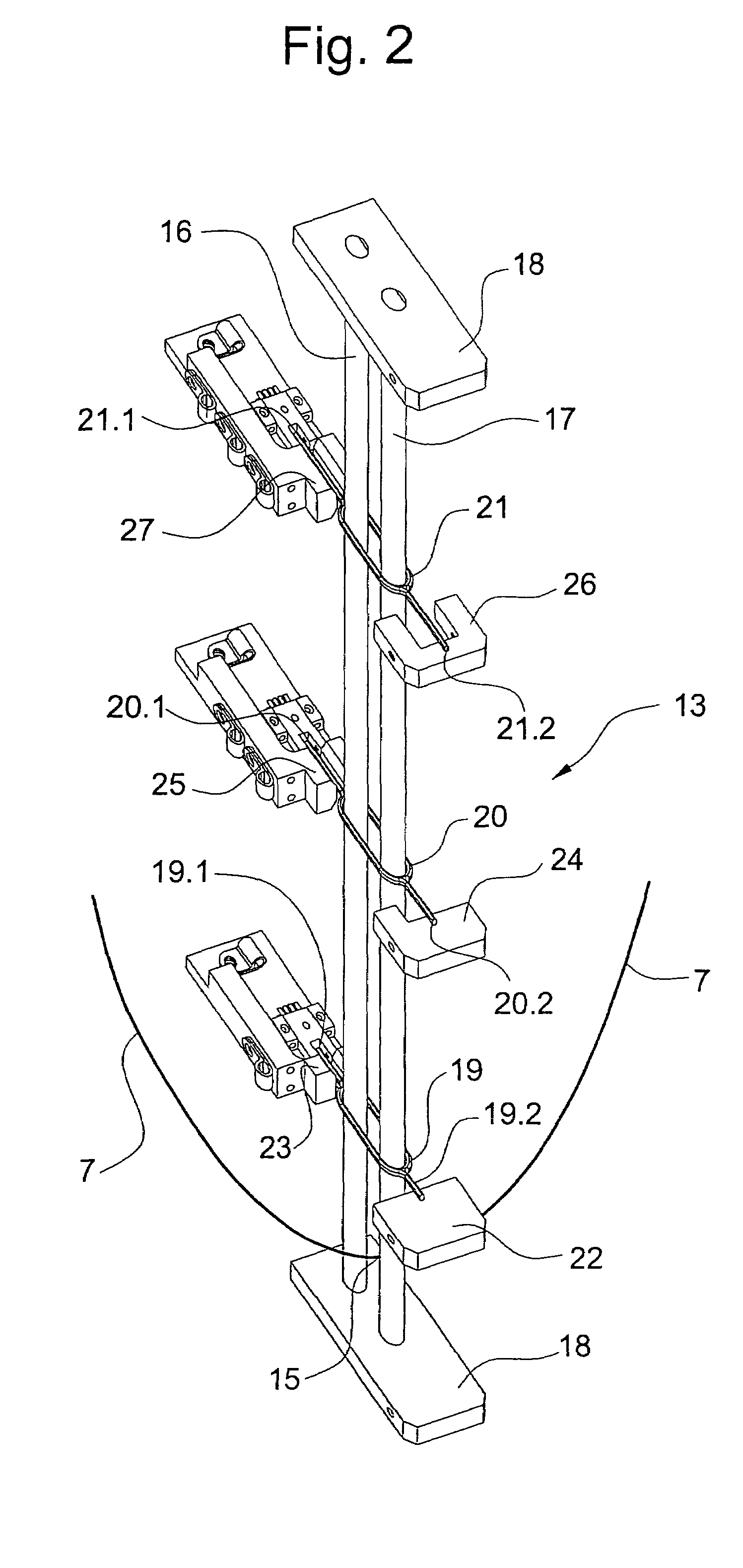
[0013]FIG. 1 shows a device for feeding wires according to the present invention including straightening device 1, a transporting device 2, a wire buffer 3, and a wire guide 4. The device is arranged on a table 5 on which a swivel unit 6 with a wire drive 6.1 is also arranged. The swivel unit 6 serves not-shown wire-processing stations of a wire-processing machine. A fine to very fine wire designated 7 is held in store in a supply drum 8. The wire store may also be in the form of a wire reel. The wire 7 is guided through a height-adjustable eye 9 that prevents the wire from swinging when the wire is withdrawn. A diverter pulley 11 arranged on a supporting bracket 10 of the straightening unit 1 realigns the wire 7 from the vertical to the horizontal, there being arranged before the diverter pulley 11 a wire-knot detector 12. Subsequently, the wire 7 passes through the straightening unit 1, which straightens the wire, bends and kinks being removed. The transporting unit 2 pulls the wi...


PUM


Abstract

A wire feeding device for very fine wire includes a straightening unit, a transporting unit, a wire buffer, and a wire guide arranged on a table on which a swivel unit with a wire drive is also arranged. The swivel unit serves wire-processing stations of a wire-processing machine. A supply of very fine wire is held in a drum and passes through the straightening unit which straightens the wire, bends and kinks being thereby removed. The transporting unit pulls the wire out of the drum and through the straightening unit and feeds the wire buffer. The wire buffer has a measuring device for monitoring a hanging wire loop. Depending on the requirement for wire in the wire-processing machine, the content of the buffer can decrease and the wire apex of the loop then moves upwards. The movement of the wire apex is detected by the measuring device and controlled with a control device via the transporting unit.

Description

BACKGROUND OF THE INVENTION[0001]The present invention relates to a wire-feeding device for a wire-processing machine, there being provided after a wire supply and before the wire-processing machine a wire buffer which can be fed by a transporting unit, the wire buffer satisfying the requirement for wire of the wire-processing machine.[0002]From German patent application DE 33 43 286 A1 an arrangement for coiling a lightwave conductor has become known. The coiling operation takes place under a constant mechanical tension. The tension is determined by the own weight of the hanging length of conductor and by an additional toroidal weight attached to it. The length of the hanging conductor and the position of the additional weight can be regulated by means of a regulating device and a detecting device. The rotational speed of the coiling reel is controlled in such manner that the length of the hanging conductor remains constant, light barriers arranged one above the other detecting the...

Claims


Application Information

Patent Timeline
Patent Type & Authority Patents(United States)
IPC IPC(8): B65H51/30B65H51/20G02B6/44
CPCB65H51/20B65H51/30G02B6/4457B65H2701/32
Inventor ULRICH, KURT
Owner KOMAX HOLDING
Learn More