Seat load measuring apparatus

a load measuring and seat technology, applied in the direction of force/torque/work measurement apparatus, instruments, tractors, etc., can solve the problems of increased production costs, troublesome mounting of sensor plates to the body of load sensors, and inability to effectively restrain the occupant in relation to the inertial force acting on the occupant, etc., to achieve improved compatibility and more efficient production

Inactive Publication Date: 2008-07-15
JOYSON SAFETY SYST JAPAN KK
View PDF32 Cites 7 Cited by
  • Summary
  • Abstract
  • Description
  • Claims
  • Application Information

AI Technical Summary

Benefits of technology

[0011]It is one of several objects of the present invention to provide a seat load measuring apparatus which can be adapted for use in various kinds of motor vehicles without requiring various load sensors to have cables of different lengths. Thus, the present invention provides improved compatibility and is more efficient to produce. Additionally, it is an object of the present invention to provide an inexpensive seat load measuring apparatus, which can be adapted for use in various kinds of motor vehicles that also withstands a large load applied to the mounting portion of the seat load measuring apparatus due to the lifting of the rear side of the vehicle seat.
[0017]According to one embodiment of the present invention a cable for connecting a load sensor and a control unit can be designed to be detachable by employing a sensor-side connector and a cable-side connector, thereby achieving the adaptability of the load sensor and the connector casing relative to various kinds of motor vehicles. The only preparation required is configuring a cable having a length corresponding to the kind of motor vehicle. Therefore, the seat load measuring apparatus can be easily and inexpensively adopted to various kinds of motor vehicles.
[0018]According to one embodiment of the present invention, by utilizing an opening of a protector which is formed in at least one side in any of the vertical direction, the longitudinal direction, the lateral direction, the diagonal direction from upper front to lower back or from lower front to upper back, the diagonal direction from upper left to lower right or from lower left to upper right, and the diagonal direction from forward left to backward right or from backward left to forward right, the load sensor can be effectively protected and the connection and disconnection between the load sensor and the cable can be facilitated. Moreover, it is not required to form hole(s) and groove(s) for insertion of the cable-side connector, thus further simplifying the manufacture and reducing the cost.
[0019]According to one embodiment of the present invention, the sensor-side connector and the cable-side connector can be delivered in the connected state. In addition, since the connectors are allowed to be connected during the assembly of a vehicle body by a car manufacturer, the connectors can be delivered separately. Moreover, the flexibility during manufacturing process is improved. In this manner, an inexpensive seat load measuring apparatus which can be effectively adopted in various kinds of motor vehicles and is easier to install, maintain and manufacture.
[0020]Further, according to one embodiment of the present invention, the protector is formed just by bending a band-like plate. Therefore, the protector can be easily and inexpensively formed. Furthermore, according to one embodiment of the present invention, a protective mechanism is provided so as to effectively withstand large load exerted on the mounting portion of the seat load measuring apparatus disposed between a vehicle seat and a vehicle floor by a moment in a direction of lifting the rear portion of the vehicle seat.

Problems solved by technology

If the seat belt device and the airbag device are invariably controlled regardless of the weight of the occupant, it is difficult to make these devices effectively restrain the occupant in relation to the inertial force acting on the occupant.
One problem frequently encountered is that in the event of a vehicle collision, large deceleration may act on a vehicle body so as to momentarily lift up the rear side of a vehicle seat where the seat load measuring apparatus is mounted.
Therefore, manufacturers must produce load sensors with varying cable lengths resulting in an increase in production costs.
Further, since the cable is attached to the load sensor, it is troublesome to mount the sensor plate to the body of the load sensor.
As a result, such a seat load measuring apparatus is difficult to install, maintain and manufacture.

Method used


Image

  • Seat load measuring apparatus
  • Seat load measuring apparatus
  • Seat load measuring apparatus

Examples


Embodiment Construction

[0042]One of many embodiments of the present invention will be described below with reference to the drawings.

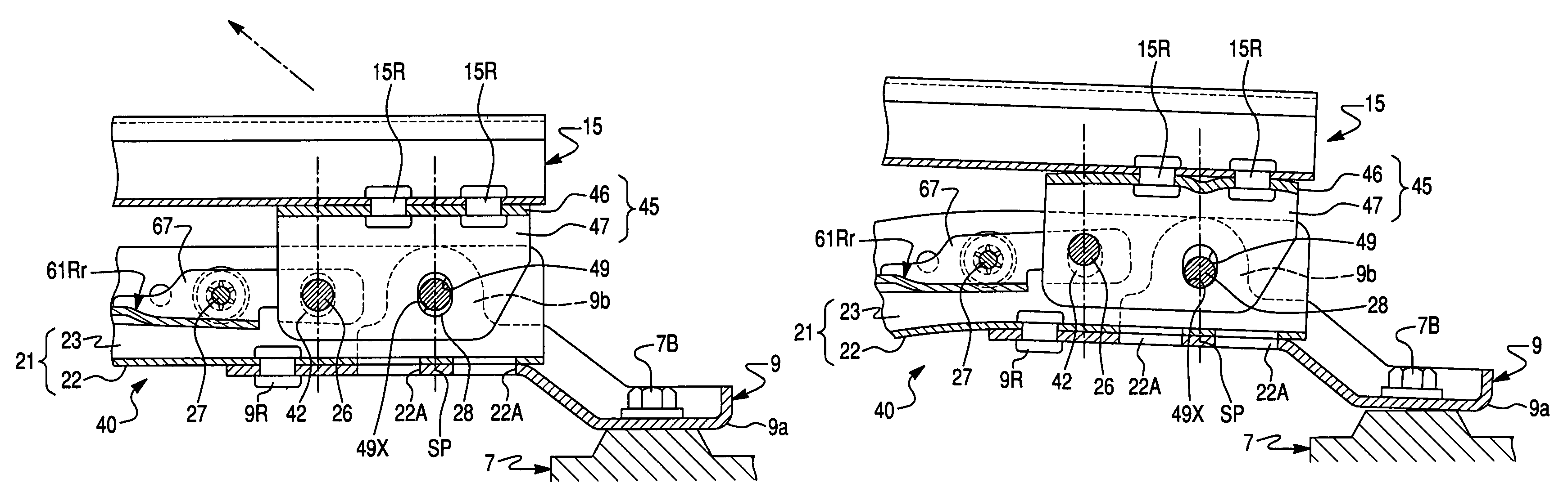
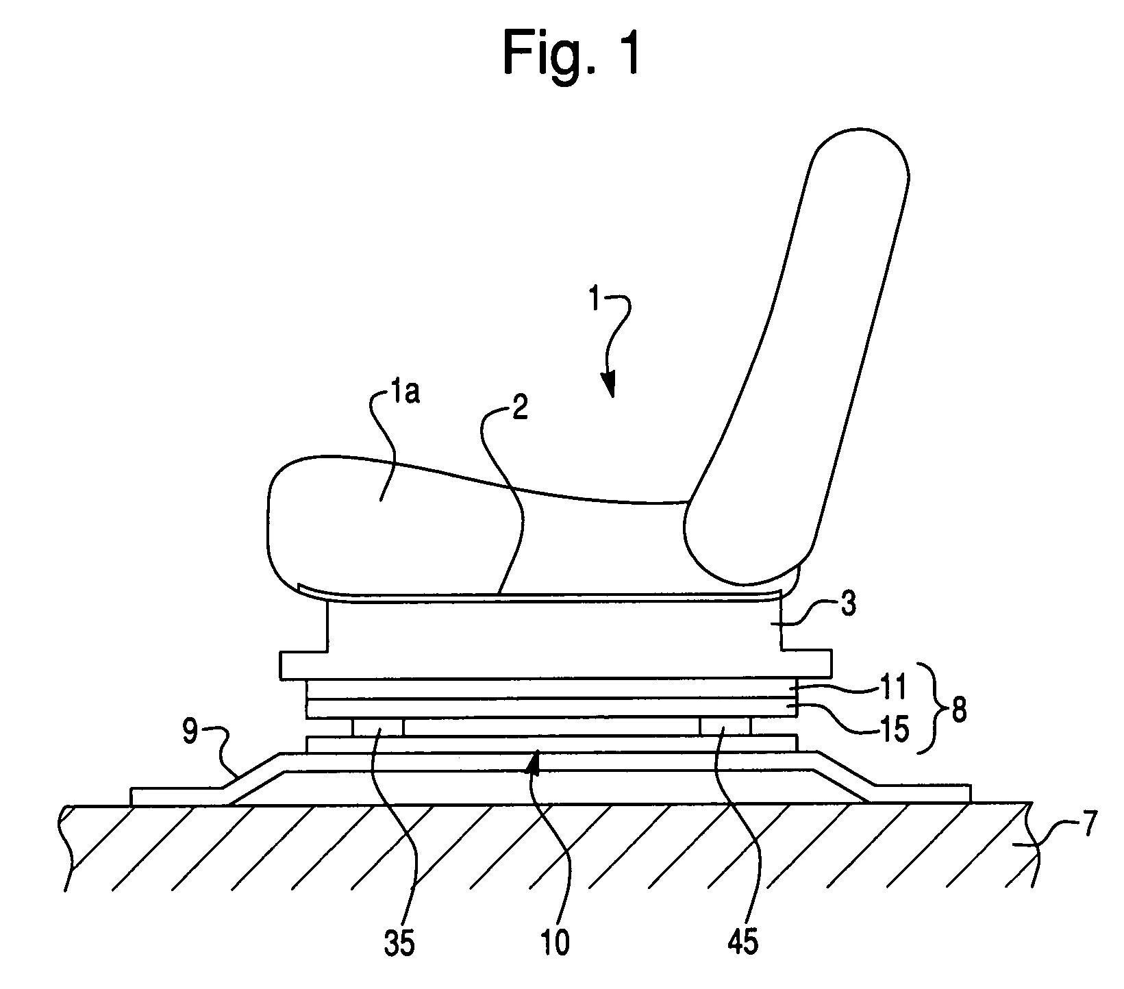
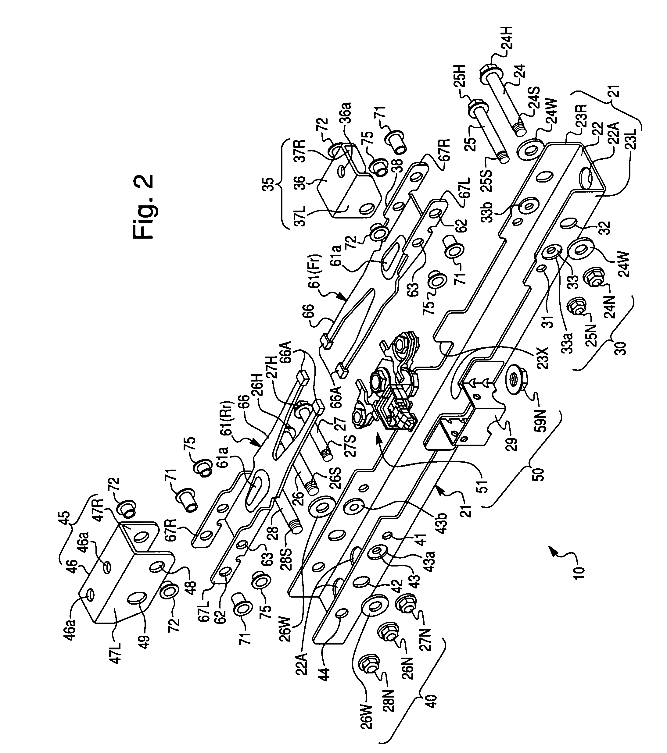
[0043]As shown in FIG. 1, a vehicle seat 1 has a seat cushion 1a on which an occupant sits, and a seat pan 2 made of a steel plate which is disposed beneath the seat cushion 1a to entirely cover the under surface of the seat cushion 1a. Under the seat pan 2, a pair of side frames 3 (only one of which is shown in FIG. 1) extend downwardly from the seat pan 2 and are spaced apart from each other at a predetermined distance in the lateral (left-to-right) direction of the vehicle. Each side frame 3 is disposed to extend in the longitudinal (front-to-rear) direction of the vehicle. Disposed on the lower ends of the side frames 3 are seat rails 8 (only one of which is shown in FIG. 1), respectively. Each seat rail 8 is a combination of an upper rail 11 which is fixed to the lower end of the side frame 3 and a lower rail 15 which is arranged to slide relative to the upper rail 11 i...


PUM


Abstract

A seat load measuring apparatus which can be effectively adopted to various kinds of motor vehicles without requiring various load sensors having cables of different lengths according to the kinds of motor vehicles, thereby providing improved installation, maintenance and manufacturing benefits. A seat load measuring apparatus may include a connector of a load sensor is a male connector having terminals projecting downwardly. The entry of the male connector faces the open bottom of a protector. On the other hand, a cable to be connected to an ECU is provided with a cable-side connector. The cable-side connector is composed of a female connector which is detachable relative to the male connector. Therefore, the load sensor and the cable are detachable from each other, thereby achieving the adaptability of the load sensor and the connector casing a relative to various kinds of motor vehicles.

Description

[0001]This application is a continuation application of U.S. application Ser. No. 10 / 644,042, filed Aug. 20, 2003.BACKGROUND OF THE INVENTION[0002]The present invention relates to a seat load measuring apparatus for measuring a seat load applied to a seat of a vehicle, such as an automobile, by the weight of an occupant sitting on the seat. Particularly, the present invention pertains to a seat load measuring apparatus which can be flexibly and effectively adopted to various kinds of motor vehicles.[0003]A conventional automobile is equipped with seat belt devices and airbag devices. These devices are provided for restraining the inertial movement of occupants so as to protect the occupants in the event of an emergency such as a vehicle collision at which large deceleration is exerted on the vehicle.[0004]The amount of the inertial force acting on the occupant depends on the weight of the occupant sitting on the vehicle seat. If the seat belt device and the airbag device are invaria...

Claims


Application Information

Patent Timeline
Patent Type & Authority Patents(United States)
IPC IPC(8): B60R21/015G01G21/00G01G19/12B60N2/00B60N2/07B60N2/90B60R21/01G01G19/414G01G19/52
CPCB60N2/002B60N2/0715B60R21/0152G01G19/4142B60R21/01516B60N2/0732
Inventor KAJIYAMA, HIROSHIKOBATA, TOSHIHIKO
Owner JOYSON SAFETY SYST JAPAN KK
Why Eureka
Try Eureka