Display device, and vehicle-mounted display device and electronic

a display device and vehicle-mounted technology, applied in the field of display devices, can solve the problems of limited design freedom, and achieve the effects of high value added, more sophistication, and more comfortable driving and safety

Active Publication Date: 2008-07-15
SEMICON ENERGY LAB CO LTD
View PDF12 Cites 6 Cited by
  • Summary
  • Abstract
  • Description
  • Claims
  • Application Information

AI Technical Summary

Benefits of technology

[0014]Further, the invention provides a vehicle which is equipped with a display device serving as a side-view mirror or a rearview mirror. In this case, the mirror function can be used mainly and the display function may be used when necessary. Thus, a vehicle which is highly sophisticated and highly value added can be provided. By installing a camera or a sensor measuring the distance between the cars in a vehicle, a driver can drive more comfortably and safely by acquiring the information as necessary.
[0018]The invention further provides a vehicle including the above display device as a side-view mirror or a rearview mirror. In this case, the mirror function can be used mainly and a display function may be used when necessary. Thus, a vehicle which is highly sophisticated and highly value added can be provided. By installing a camera or a sensor measuring the distance between the cars in a vehicle, a driver can drive more comfortably and safely by acquiring the information as necessary.

Problems solved by technology

Accordingly, the design freedom is limited.

Method used


Image

  • Display device, and vehicle-mounted display device and electronic
  • Display device, and vehicle-mounted display device and electronic
  • Display device, and vehicle-mounted display device and electronic

Examples


embodiment mode 1

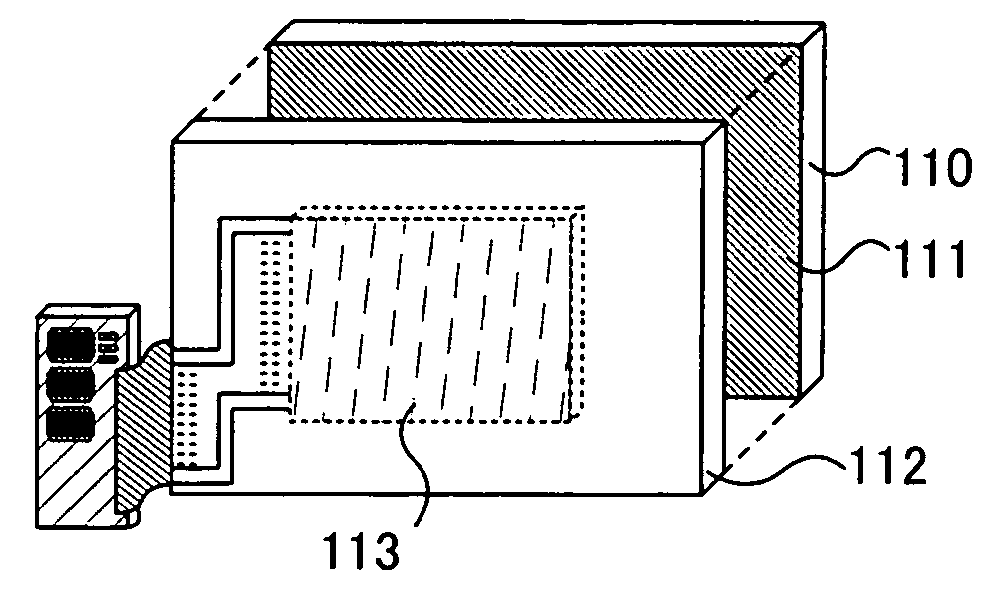
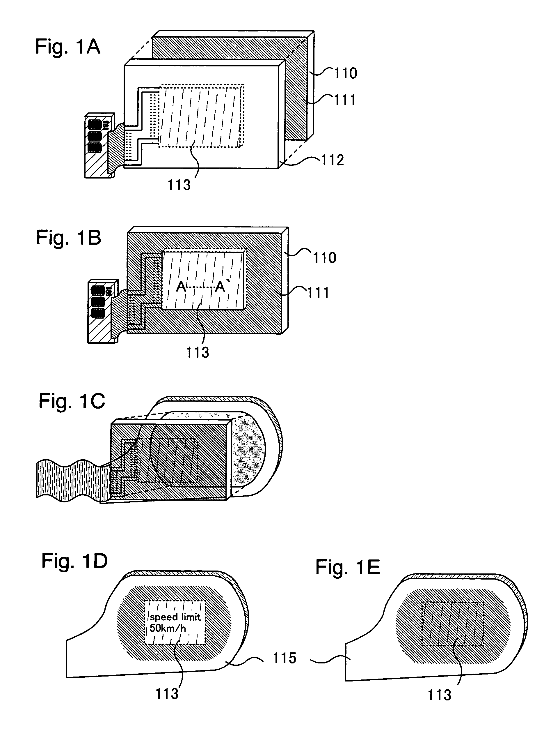
[0029]A display device of the present invention will be described with reference to FIGS. 1A to 1E. A display device of the present invention has substrates 110 and 112, a reflection coating 111, and a display area 113. As is shown, the structure of a display device of the invention is roughly divided into two types, one is a structure in which the substrate 110 having the reflection coating 111 and the substrate 112 having the display area 113 are stacked together (FIG. 1A). Note that the expression “stacked together” includes a state where the substrate 110 and the substrate 112 are stuck together with no space therebetween, with a transparent material such as resin provided therebetween, with gas such as an inert gas supplied into the space, or the like. In this structure, a plurality of substrates; at least one of them is provided with the reflection coating 111 and the another at least one of them provided with the display area 113 are used.

[0030]Another is a structure in which...

embodiment mode 2

[0050]This embodiment mode will be described with reference to FIGS. 4A to 5C.

[0051]FIG. 4A is a top view of a vehicle. FIG. 4B is a side view of the vehicle viewed from the front. FIG. 4C is a side view of the vehicle viewed from the back. In FIGS. 4A to 4C, the vehicle has cameras 121, 122, 125, and 126, side-view mirrors 123 and 124, lights 127 and 128, a rearview mirror 129, and sensors 130, 131, 134, and 135. Further, it is not illustrated; however, the vehicle is equipped with an energy source such as electricity or gasoline, a motor such as an engine, a power transmission device, a braking device, a steering system, a suspension system, auxiliaries, and accessories. Note that the number and the position of a camera, a sensor, and a microphone can be determined arbitrarily without limitation to the illustrated case.

[0052]It is preferable to use a camera equipped with a fisheye lens for the cameras 121, 122, 125, and, 126; thus, 360 degrees in all directions can be photographed...

embodiment mode 3

[0058]As an example of electronic devices manufactured according to the present invention, a digital camera, a sound reproduction apparatus such as a car audio, a note book type personal computer, a game machine, a portable information terminal (a cellular phone, a portable game machine, and the like), and an image reproduction device equipped with a recording medium such as a home video game machine can be noted. The specific examples thereof are described with reference to FIGS. 6A to 6C.

[0059]FIG. 6A is a portable terminal, which includes a body 9301, a voice output portion 9302, a voice input portion 9303, a display area 9304, an operation switch 9305, an antenna 9306, and the like. When a light-emitting device of a self luminous type is used as a display element provided for the display area 9304, since a back-light and the like is not needed, thin, small and light display area can be obtained as compared with the case of using a liquid crystal element, thereby being extremely ...


PUM


Abstract

To provide a display device, a vehicle-mounted display device, and an electronic device whose chassis are not large with much design freedom. In the present invention, a plurality of light-emitting elements each having a luminescent material sandwiched between a pair of electrodes having transparency, a plurality of liquid crystal elements each having a liquid crystal material sandwiched between a pair of electrodes having transparency are arranged in a display device over a substrate having a mirror surface. Further, a plurality of light-emitting elements each having a luminescent material sandwiched between a pair of electrodes having transparency, a plurality of liquid crystal elements each having a liquid crystal material sandwiched between a pair of electrodes having transparency are arranged in a display device over a substrate having a reflecting surface. The display device is secured to the substrate with a barrier film therebetween.

Description

BACKGROUND OF THE INVENTION[0001]1. Field of the Invention[0002]The present invention relates to a display device that includes a display element having a transparent electrode. Further, the invention relates to a vehicle used for transport of people or goods and to an electronic device with the use of the display element of the present invention. Still further, the invention relates to a vehicle-mounted display device.[0003]2. Description of the Related Art[0004]There is a technique in which sight to be reflected in a side-view mirror or a rearview mirror provided for a vehicle is increased by applying a display device to the mirror (Reference 1: Japanese Patent Laid-Open No. 2002-200936 (FIGS. 4, 5, 16, and 17)). In Reference 1, the following structures are disclosed: the first structure in which a display device itself which is provided on a side-view mirror or the like is used as a mirror, the second structure in which reflection of display is seen in a half mirror or the like, ...

Claims


Application Information

Patent Timeline
Patent Type & Authority Patents(United States)
IPC IPC(8): G08B5/00G09G3/00G09G3/20
CPCG09G3/20G09G2300/0842G09G2300/046
Inventor WATANABE, YASUKOTACHIMURA, YUKO
Owner SEMICON ENERGY LAB CO LTD
Why Eureka
Try Eureka