Stereo door sensor

a door sensor and stereo technology, applied in the field of machine vision systems, can solve the problems of not directly determining the direction or velocity of objects, not well suited to certain applications, prohibitively expensive, etc., and achieve the effect of reducing excessive blind spots and being convenient to us

Inactive Publication Date: 2008-07-15
COGNEX TECH & INVESTMENT
View PDF53 Cites 53 Cited by
  • Summary
  • Abstract
  • Description
  • Claims
  • Application Information

AI Technical Summary

Benefits of technology

[0022]The present invention also features elimination of excessive blind spots. A non-stationary background like the door opening motion itself (into the outbound area) can be effectively masked out by first detecting the doorframe and then simply

Problems solved by technology

Such sensors are not well suited for certain applications because they are easily circumvented.
Similarly, they can not directly determine an object direction or velocity.
These sensors often have problems maintaining uniform sensitivity throughout a monitored space or over time, and they can be prohibitively expensive.
These systems can be too slow, expensive or unreliable for most c

Method used


Image

  • Stereo door sensor
  • Stereo door sensor
  • Stereo door sensor

Examples


Embodiment Construction

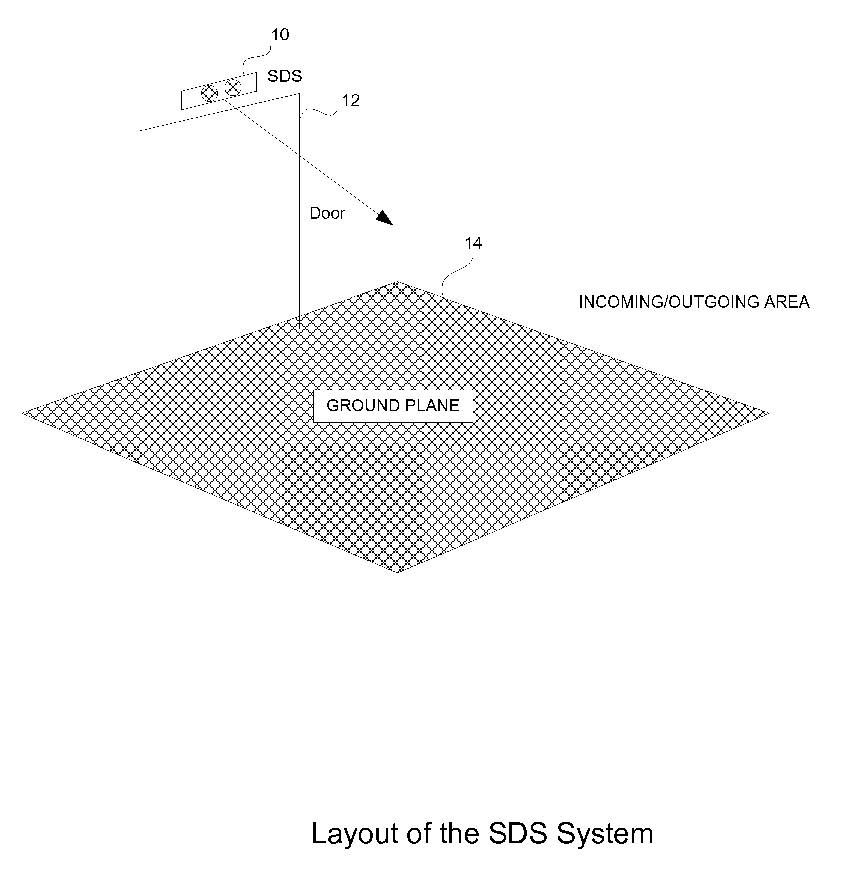
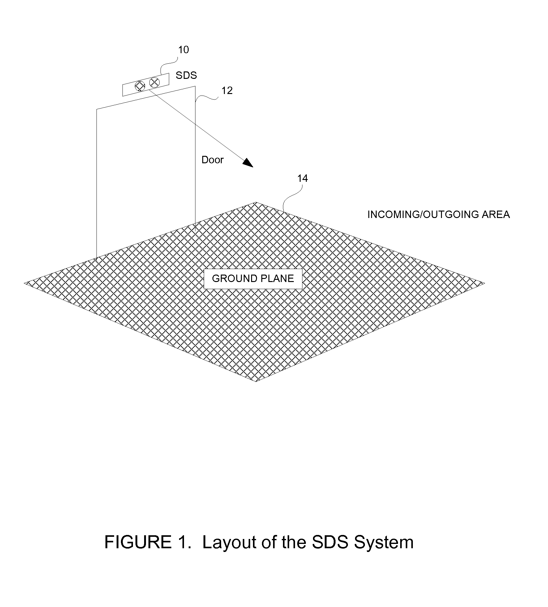
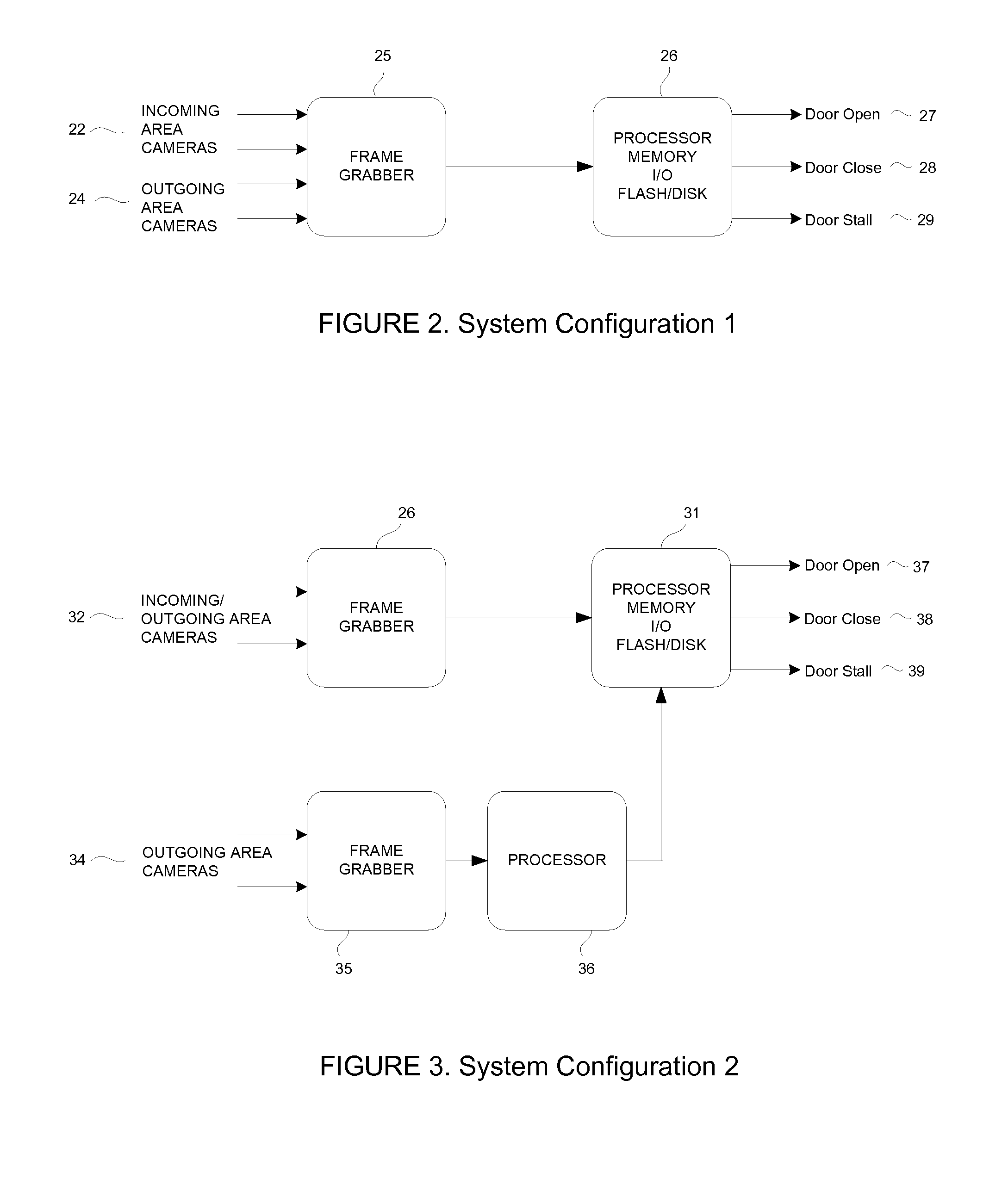
[0030]The layout of an illustrative embodiment of the present invention is described with reference to FIG. 1. The illustrative embodiment includes a set of stereo cameras 10 mounted on the top of a doorframe 12 looking downward and outward towards the incoming area 14. Optionally, another set of cameras (not shown) can be mounted on the other side of the doorframe looking at the outgoing area. The invention is calibrated to provide heights above the ground plane for any point in the field of view. Therefore, when any object enters the field of view, it generates interest points called “features”, the heights of which are measured relative to the ground plane. These points are then clustered in 3D space to provide “objects”. These objects are then tracked in multiple frames to provide “trajectories”. Such a system could then operate the door (open, close, stall) based on the various pieces of information generated about the object.

[0031]In the illustrative embodiment, the following ...


PUM


Abstract

A stereo imaging based vision system to monitor the area on the two sides of either a door and control door motion according to the motion of 3D objects in the viewing area. The system calibrated to provide heights above the ground plane for any point in the field of view. Therefore, when any object enters the field of view, it generates interest points called “features”, the heights of which are measured relative to the ground plane. These points are then clustered in 3D space to provide “objects”. These objects are then tracked in multiple frames to provide “trajectories”. Such a system could then control the door motion (open, close, stall) based on the various pieces of information generated about the object.

Description

CROSS REFERENCE TO RELATED APPLICATION[0001]This application claims the benefit of U.S. Provisional Patent Application Ser. No. 60 / 408,266, entitled “Stereo Door Sensor,” filed on Sep. 5, 2002.FIELD OF THE INVENTION[0002]The present invention relates to machine vision systems and more particularly to a method and apparatus using an automated stereo vision system to control operation of a door.BACKGROUND OF THE INVENTION[0003]Various sensors are known for use in automatic object detection and control systems. For example, photo voltaic sensors detect objects interrupting a beam of visible or UV light. Mechanical switches and load cells detect objects through direct or indirect contact or by detecting an object weight. Thermal sensors detect objects radiating heat, and electro-magnetic sensors detect objects such as metal objects that alter electromagnetic fields. These sensors typically send signals to logic circuits which control mechanical actuators, record the object's presence an...

Claims


Application Information

Patent Timeline
IPC IPC(8): G06K9/00E05F15/20G01V8/10G06T1/00G06T7/00G06T7/20
CPCG06K9/00771E05F15/73E05F2015/767E05Y2900/132G06V20/52H04N17/00
Inventor NICHANI, SANJAYSCHATZ, DAVESILVER, WILLIAM
Owner COGNEX TECH & INVESTMENT
Why Eureka
Try Eureka