Method and apparatus for first-order polarization mode dispersion compensation

a compensation method and dispersion technology, applied in the field of optical transmission, can solve the problems of significant problems, existing methods for avoiding fading in the optical transmission system, and may be sufficiently high to induce eye-closure penalties, so as to reduce the response time of the actuator used and reduce the complexity of the algorithm

Inactive Publication Date: 2008-07-22
ERICSSON TELECOMMUNICACOES SA
View PDF13 Cites 12 Cited by
  • Summary
  • Abstract
  • Description
  • Claims
  • Application Information

AI Technical Summary

Benefits of technology

[0013]The present invention provides a method and apparatus for compensating for Polarization Mode Dispersion in an optical transmission system that reduces the response time of actuators used in the apparatus; and, at the same time, that reduces the complexity of the algorithm used to control the apparatus as compared to known compensation apparatus.
[0015]With the present invention, an independent control signal is associated with each actuator of the PMD compensation apparatus. As a result, all of the actuators can be operated simultaneously; and this permits the overall response time of the compensation apparatus to be significantly reduced. Accordingly, the compensation apparatus of the present invention is better able to track and to adjust for rapid changes in the PMD of the optical fiber.

Problems solved by technology

This dispersion may be sufficiently high to induce eye-closure penalties in an optical transmission system incorporating an optical fiber.
However, measuring or monitoring the input PSP requires access to and communication between both ends of the optical fiber; and, in many applications, this can present a significant problem.
In general, existing methods for avoiding fading in an optical transmission system encounter two related problems, random fluctuations of the Principal States of Polarization and random fluctuations of the Differential Group Delay.
A disadvantage of this method is that only the mean value of the DGD is compensated for.
Moreover, when the DGD of the fiber becomes small, the compensator will actually degrade the performance of the optical transmission system.
A problem that still remains with this approach, however, is how to control the polarization transformer to automatically perform adjustment of the axes.
In general, problems arise in many existing compensation methods when the states of polarization of the optical transmission system change rapidly; and limits in the response time of the compensator restricts its ability to follow these rapid changes.
Frequently, the response time can be too long for the optical transmission system to maintain its synchronization.
The principal factors that limit the response time in various proposed compensation apparatus include the response time of materials used in actuators of the apparatus, and the complexity of the algorithm used to control the operation of the apparatus.

Method used


Image

  • Method and apparatus for first-order polarization mode dispersion compensation
  • Method and apparatus for first-order polarization mode dispersion compensation
  • Method and apparatus for first-order polarization mode dispersion compensation

Examples


Embodiment Construction

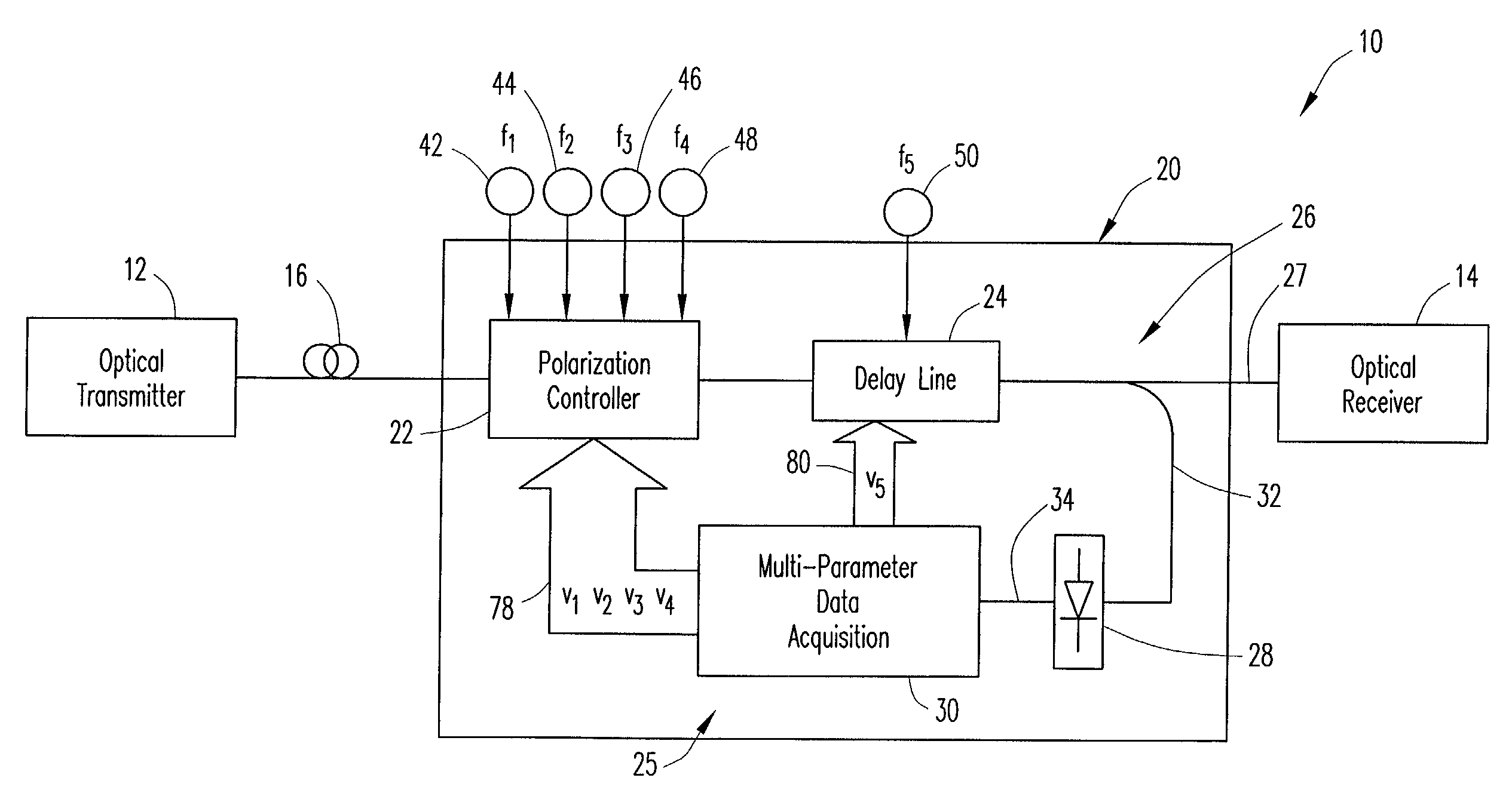
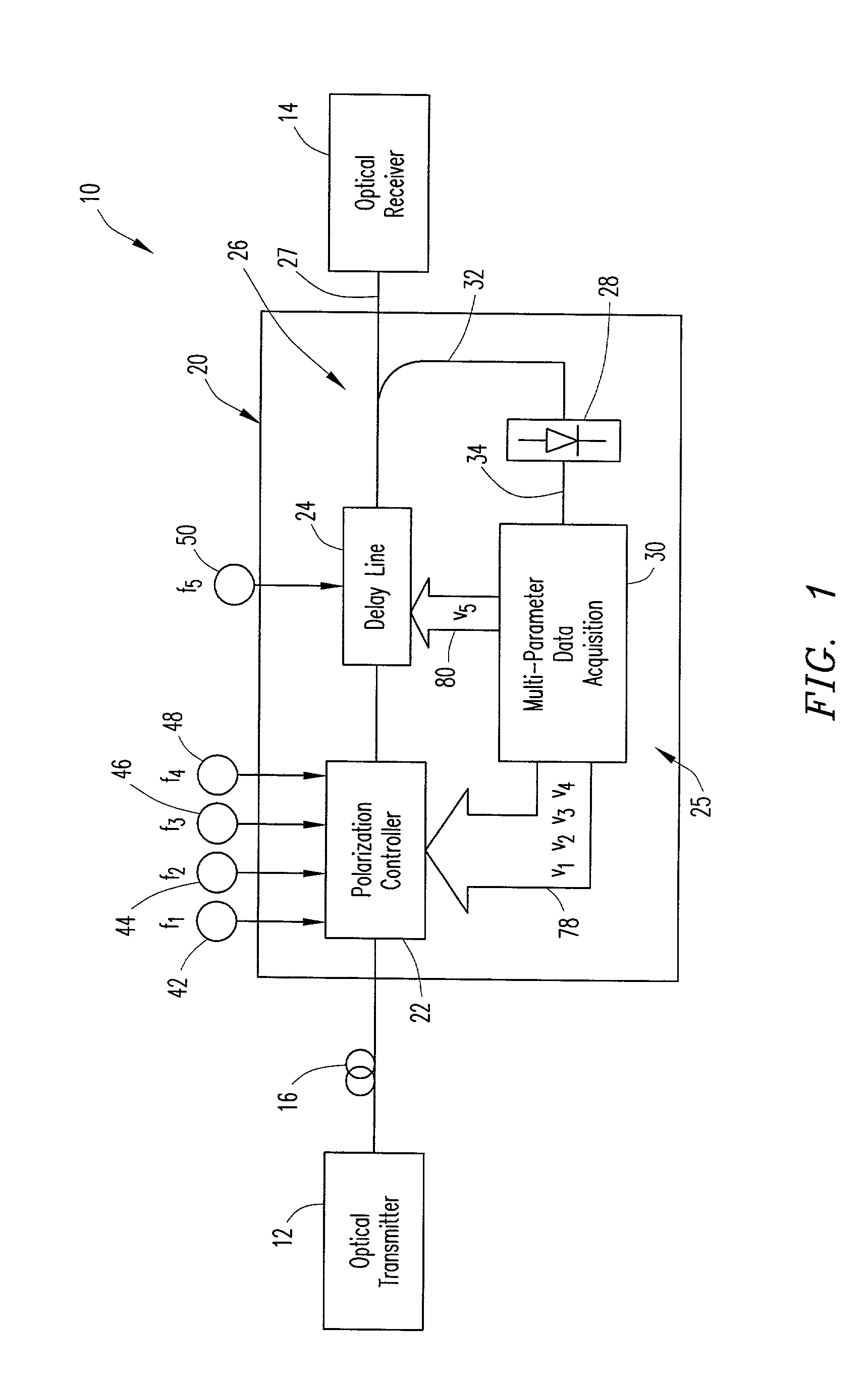
[0022]FIG. 1 is a block diagram that schematically illustrates an optical transmission system that incorporates a Polarization Mode Dispersion (PMD) compensation apparatus according to a presently preferred embodiment of the present invention. The optical transmission system is generally designated by reference number 10, and includes a B Gb / s optical transmitter 12, where B is a clock frequency of the system, a B Gb / s optical receiver 14 and an optical fiber 16 for transmitting an optical signal from the transmitter to the receiver.

[0023]The PMD compensation apparatus is generally designated by reference number 20, and functions to compensate for first-order PMD in an optical signal transmitted through the optical fiber 16 of the optical transmission system 10. PMD compensation apparatus 20 is incorporated into the optical transmission system between the transmitter and receiver, and generally comprises an automatic polarization controller 22, a variable delay line 24, and a feedba...


PUM


Abstract

Method and apparatus for compensating for first-order Polarization Mode Dispersion in an optical transmission system. An apparatus has a polarization controller for transforming polarization components of an optical signal carried by the optical fiber into orthogonal polarization states, a variable delay line for introducing a variable differential time delay between the polarization states and for producing an output optical signal that is compensated for PMD in the optical fiber, and a feedback unit for adjusting the polarization controller and the variable delay line to compensate for variations in the PMD of the optical fiber, the feedback unit including apparatus for generating a plurality of independent control signals to independently control actuators of the polarization controller and the variable delay line. The invention provides for a reduction in response time of the actuators and a reduction in complexity of an algorithm used to control the apparatus.

Description

BACKGROUND OF THE INVENTION [0001]1. Field of the Invention[0002]The present invention relates generally to the optical transmission field. More particularly, but not by way of limitation, the present invention relates to a method and apparatus for compensating for first-order Polarization Mode Dispersion in an optical transmission system.[0003]2. Description of the Prior Art[0004]Polarization Mode Dispersion (PMD) is the residual dispersion that arises in optical fibers because the degeneracy of the polarization modes within the fundamental spatial mode is leveled by small asymmetric stresses along the fiber. This dispersion may be sufficiently high to induce eye-closure penalties in an optical transmission system incorporating an optical fiber. When a sharp spectrum optical signal, such as is employed, for example, in WDM (Wavelength Division Multiplexing) transmissions, travels along an optical fiber; the signal can be described as being composed of the fastest and the slowest po...

Claims


Application Information

Patent Timeline
Patent Type & Authority Patents(United States)
IPC IPC(8): H04B10/00G02B6/34H04B10/02H04B10/18
CPCG02B6/274H04B10/2569G02B6/278
Inventor VON DER WEID, JEAN PIERRELINARES, LUIS CARLOS BLANCODE FARIA, GIANCARLO VILELA
Owner ERICSSON TELECOMMUNICACOES SA
Why Eureka
Try Eureka